
Stainless Steel Cross Guide Rail Clamp
The stainless steel cross guide rail clamp joins intersecting guide-support members. Selecting both openings together keeps the vertical support and horizontal guide position aligned.
- Material
- Stainless steel
- Connection
- Cross clamp
- Selection
- Both rod openings
Measure each rod separately and show which one runs vertically. The two clamp openings need to match the members they hold.
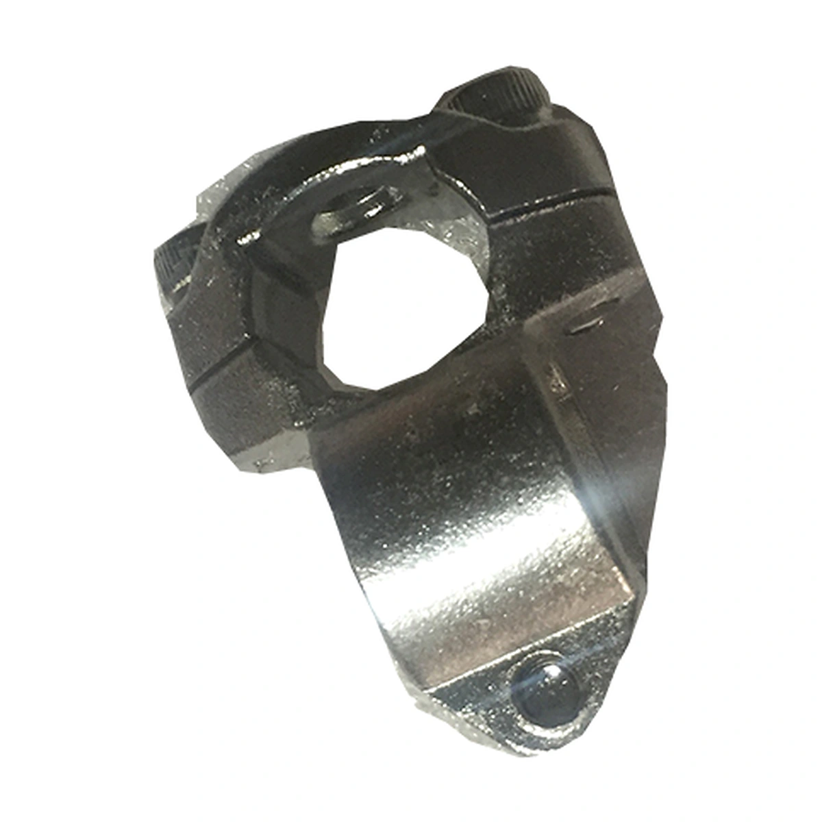


Connect the Support Rod to the Guide Adjustment
The cross clamp connects two members at an intersection. One member can carry the support while the other sets the guide reach. Clamping the members fixes their relative positions within the guide assembly.
Both openings matter when replacing this part. An assembly may use equal rod sizes or a transition between different sizes. Check the actual rods and the required orientation before choosing the clamp, including the space needed to reach its fasteners.
Specifications
| Parameter | Specification |
|---|---|
| Material | Specification: Stainless steel |
| Connection type | Specification: Cross clamp |
| Selection inputs | Specification: First rod size, second rod size and orientation |
Dimensions & Fit
Measure the outside diameter of each member at the clamping location. Include any flat, sleeve or non-round feature that changes how it seats.
Check the rod overlap and the fastener access after the rail reaches its operating position. Leave sufficient engagement within both openings; a rod end should not sit partly outside the clamping region.
Position a Rail From a Cross-Rod Support
In a guide assembly, the cross connection links the support height to the sideways reach of the rail. Adjusting one member can shift the guide while the other remains attached to the conveyor.
After a format change, check that both members are seated and secured. Product side pressure passes through this connection to the support, so clamp fit needs review with the complete guide arrangement.
Request a Cross-Clamp Quote
Send both rod diameters, their orientation and a photograph of the existing cross connection. Include quantity and the required guide reach.