
Beam Spacer Kit
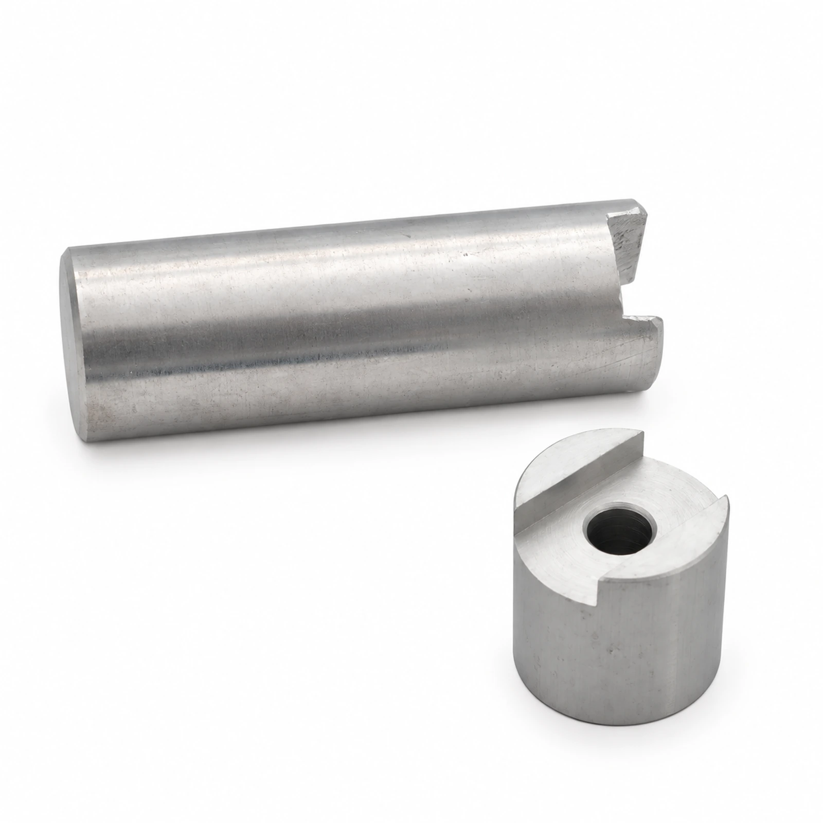
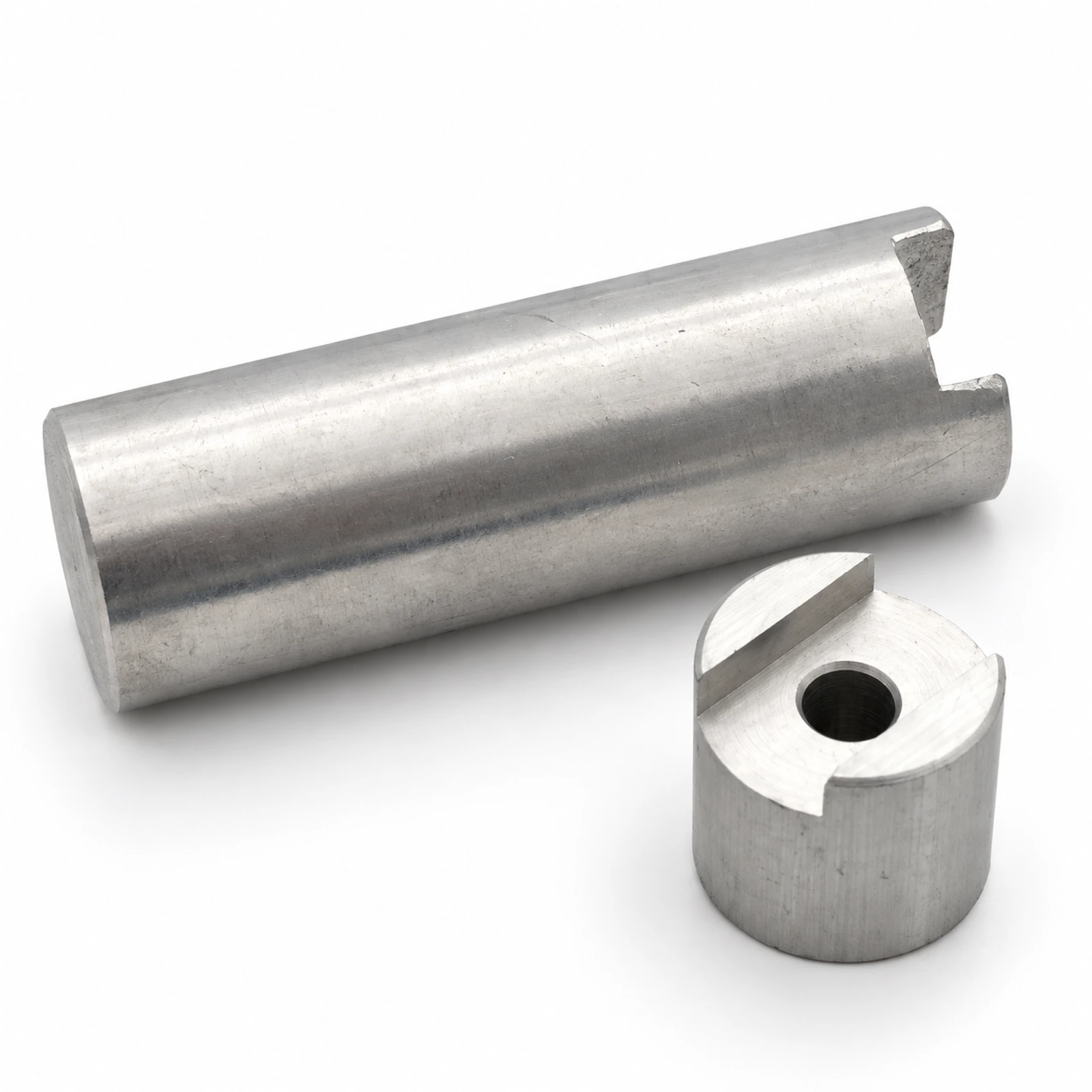
CSTRANS supplies connecting columns for paired flexible-chain conveyor beams. An 85 main beam can be joined to an 85 half-beam, with the column locating the two sections together. The larger 145, 175 and 295 beam series use connecting columns of different lengths. Choosing the column for the actual beam arrangement matters where a bend or split-beam section must continue the chain's running path.
85 beam joint
Join the 85 main and half-beam
The 85 main beam and 85 half-beam form a combined section in the CSTRANS flexible-chain system. A connecting column joins them. The half-beam is used mainly in horizontal and vertical bends, so this connection is part of how a curved track meets its main beam. Keeping the two sections in their intended relative position gives the chain and wear strip a continuous route through the joint instead of forcing a change in track level or lateral position.
Series lengths
Respect length differences between larger series
CSTRANS identifies different connecting-column lengths for the 145, 175 and 295 beam series. That difference prevents a larger-series column from being treated as a universal spacer. Its length relates to the separation of the paired beam pieces and therefore to the assembled section's geometry. When a column is replaced, the beam series is the first reliable reference; the actual installed length and attachment pattern determine whether a particular part will fit the existing assembly.
Bend alignment
Keep the bend junction aligned with the line
A spacer column sits inside a larger system of beam joints, wear strips, supports and guides. At a bend entry, the supported chain has to pass from a straight main beam into the curved section; at the exit, it must return to the next straight. A column that places the paired beam pieces correctly helps maintain those transition points. CSTRANS can coordinate the column with the beam series and bend geometry so the product stays on the intended carrying path toward the next machine.
Application / Line Context
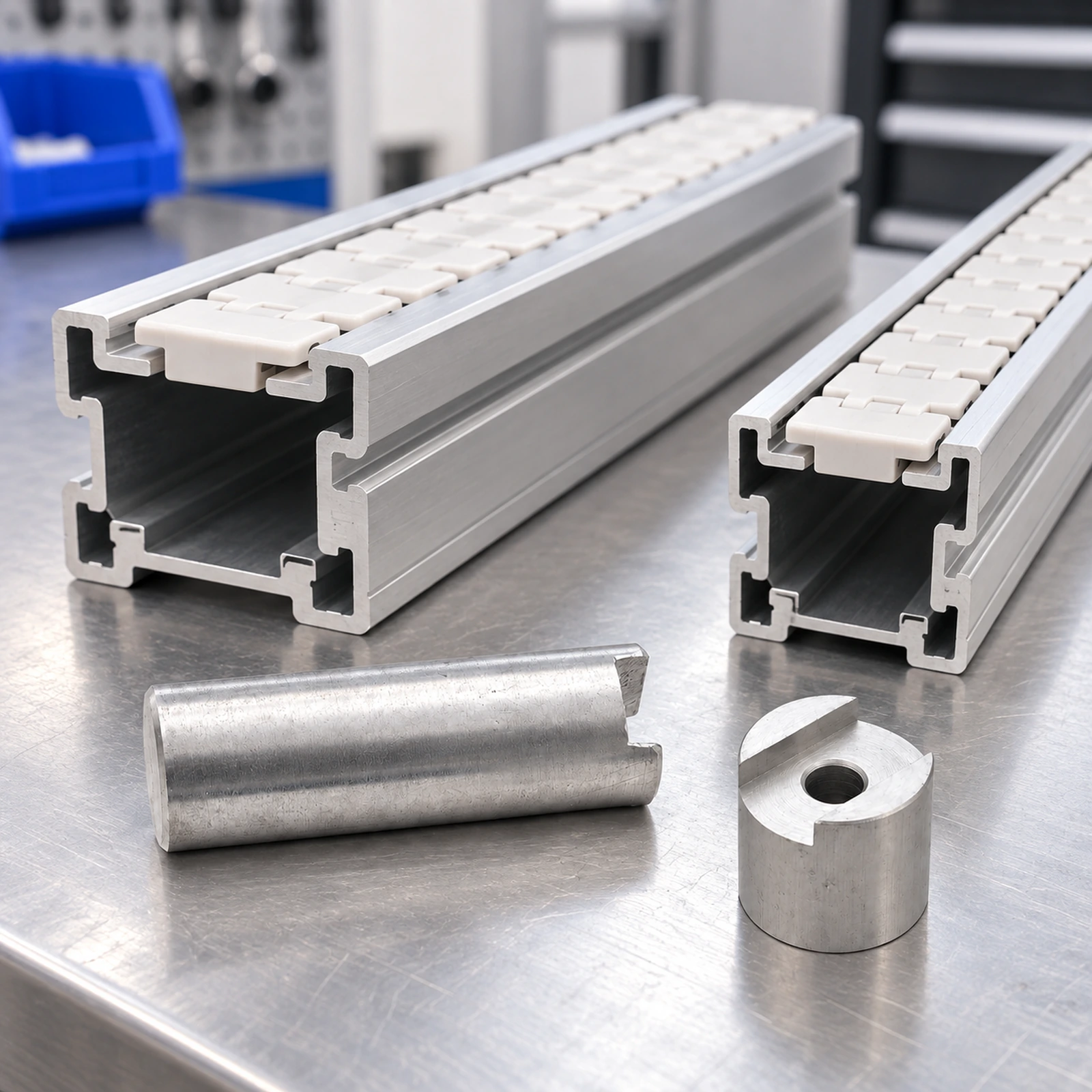
On a route that turns around a machine, an 85 main-and-half-beam assembly positions the chain track through the curve. The column keeps the paired sections related while support brackets hold the assembled beam above the frame. The wear strip and guide then follow that geometry as products travel around the corner. Where the route changes level, the same main-to-half-beam principle applies to the vertical bend, but the lead-in, angle and centerline radius still set the exit position. A replacement column from a different beam family may alter the geometry even if it resembles the removed part. At discharge, the resulting beam position affects the receiving height and product handoff.