
203 External-Joint Articulated Conveyor Foot
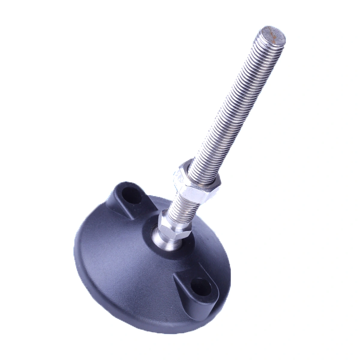
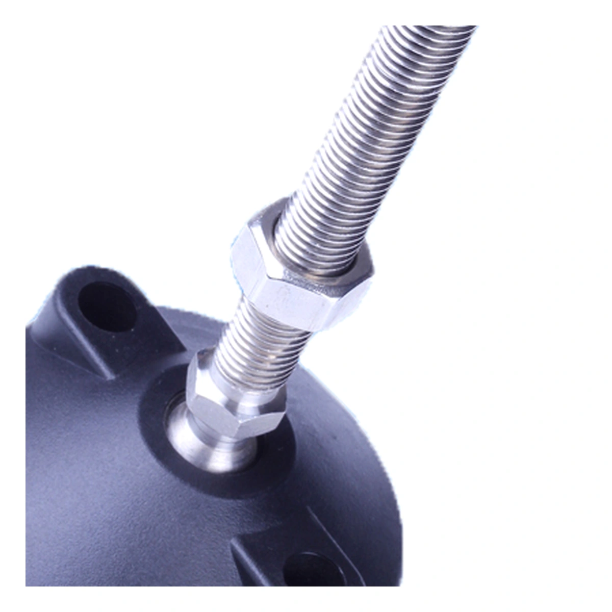
The 203 foot places an articulated connection above a nylon base. Its exposed joint arrangement lets the base change angle relative to the threaded stem, with an additional nut shown above the joint.
- Code
- 203
- Thread Family
- M8–M24
- Joint Position
- Above the base
Leave Clearance Around the External Joint
Check the space above the base for joint movement and nut access at the required support height.
Keep the Joint Clear Above the Base
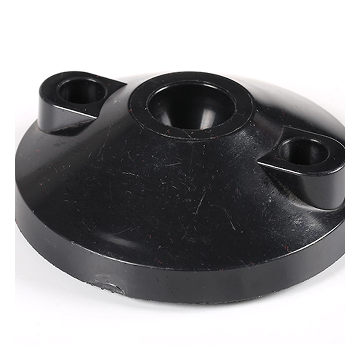
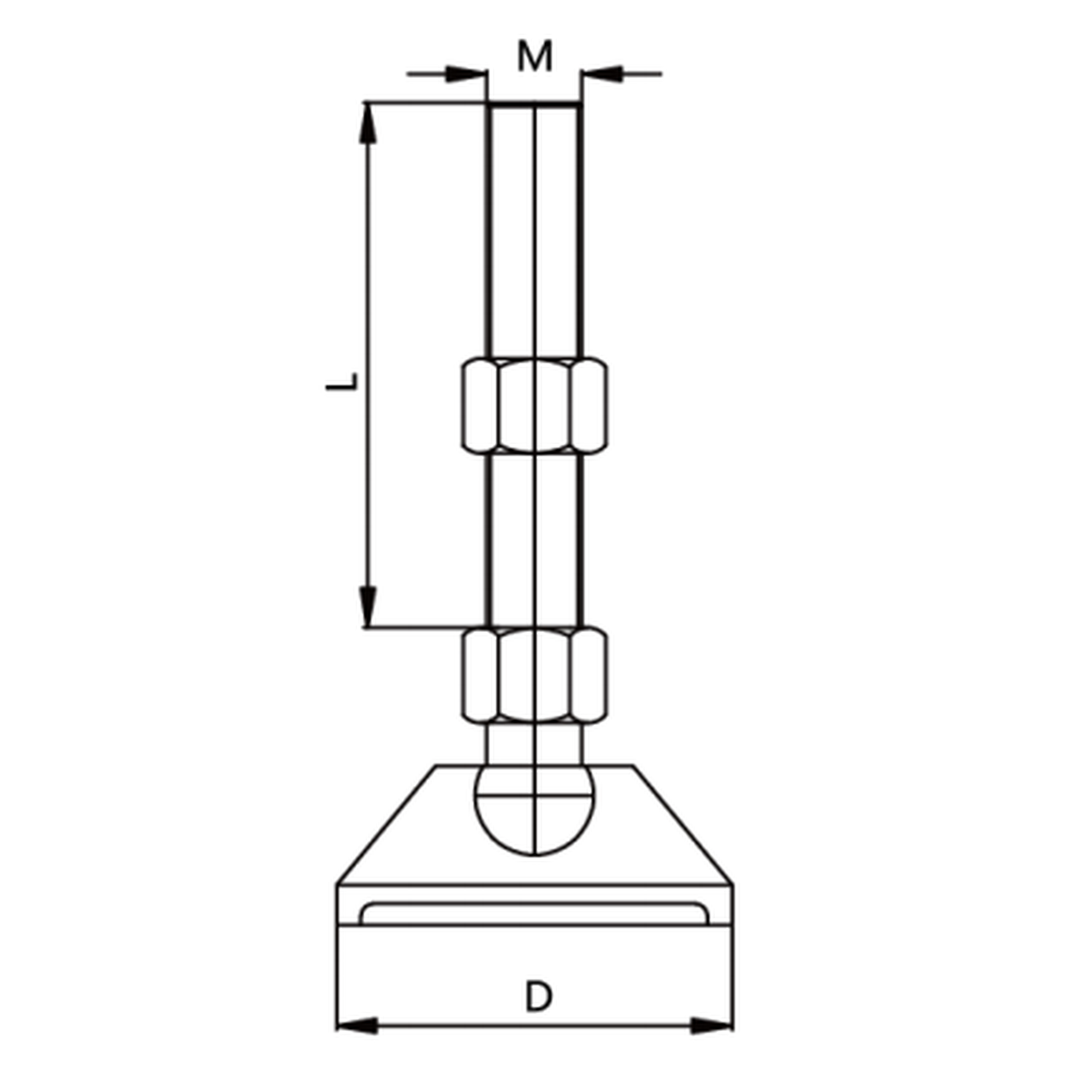
The 203 connects the stem to an articulated base with the joint visible above it. The drawing shows an additional nut near that connection. This arrangement needs room around the base as well as along the adjustable stem.
The base angle and support height are separate selection checks. Articulation accommodates the floor angle; the threaded connection establishes height. Confirm both against the installed support rather than choosing only by stem diameter.
Specifications
| Parameter | Specification |
|---|---|
| Code | Specification: 203 |
| Base material | Specification: Nylon |
| Metal material options | Specification: Stainless steel / carbon steel |
| Thread family | Specification: M8–M24 |
| Stem-length family | Specification: 75–250 mm / 2.953–9.843 in |
| Construction | Specification: External-joint articulated foot |
Confirm base size, stem and nut arrangement as one assembly.
Review the Base and Nut Envelope
Show the receiving thread and required installed height. Check engagement and the position of the upper locknut. Allow access to the lower nut without restricting the joint's intended movement.
Compare the base seat with the floor slope and the space around the upright. Review vertical loading and horizontal forces with the complete support arrangement; no angular range should be assumed from the appearance of the joint.
Adjustable Support with an Accessible Joint Area
The 203 can be considered where a conveyor support requires an articulated base and the external connection suits the available installation space. The raised joint and lower nut affect how close adjacent hardware can sit to the base.
When several supports are leveled, inspect base seating and remaining thread engagement at each position. Floor slope and frame alignment should be checked together before locking the settings.
Review a 203 Foot Assembly
Send the required thread, stem length, base dimensions and quantity. Include a support section, installed height and floor conditions so CSTRANS can check the joint clearance.