

Opens in a new tab

Electronics Assembly Conveying

Conveyor chains, modular belts and supporting hardware for trays, fixtures and electronic assemblies moving between production stations.

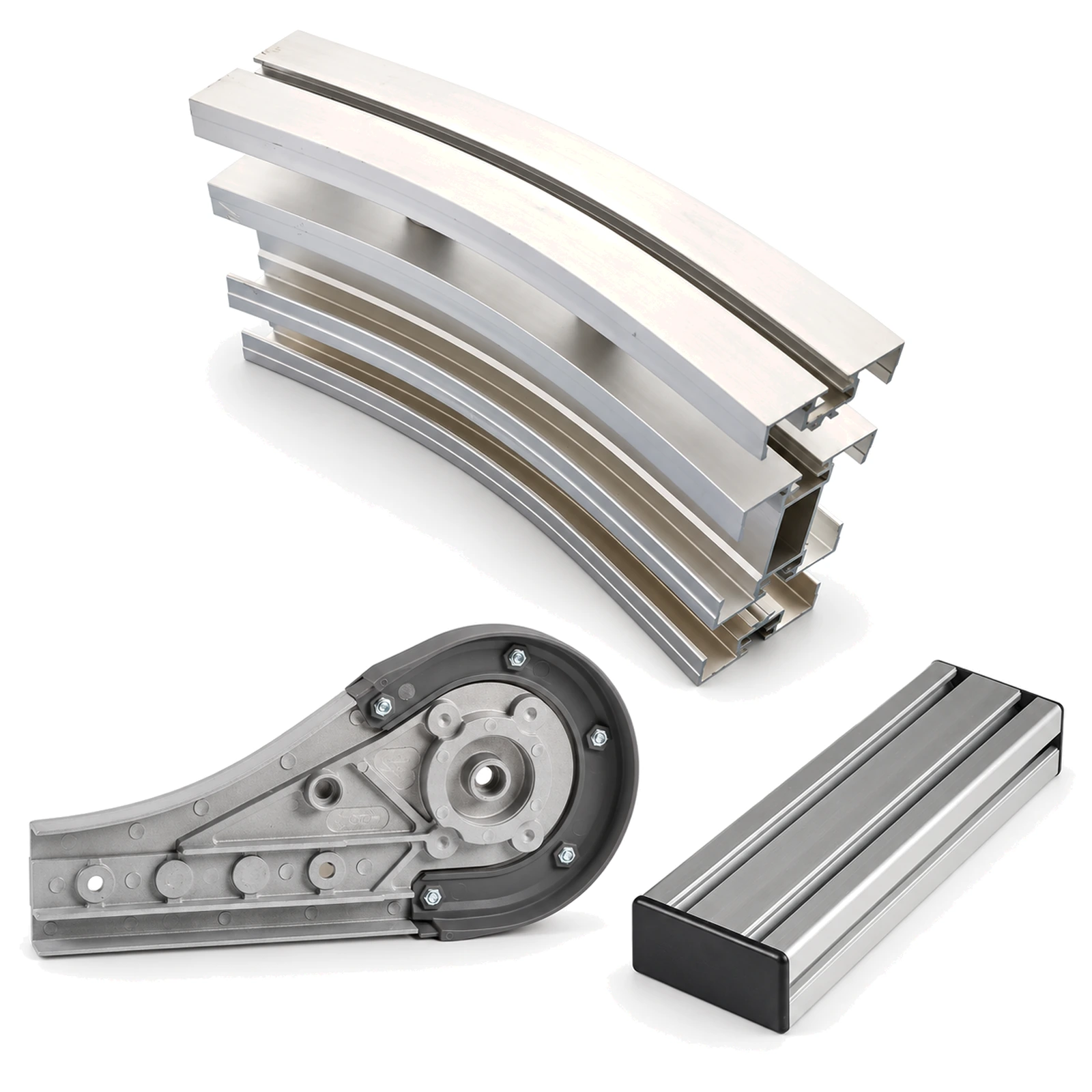
Flexible-chain bend, end unit and beam components

Define How the Assembly Is Carried

An exposed circuit board, a housed module and a loaded tray have different contact restrictions. A tray or fixture provides a defined contact surface for transport, testing and packing.

We supply chains, modular belts, sprockets, guides and flexible-chain hardware. Antistatic material options are available for selected chains and belts. Our technical support covers part matching and application-specific material requirements.

Carrier Support, Static Control and Station Interfaces

Contact Beneath the Product or Carrier

Connectors and components projecting below an assembly affect where it can rest. For tray handling, the tray’s feet or runners determine the supported footprint.

Use underside drawings to define the contact areas. Check chain or belt width, transfer gaps and guide clearance against those areas and any permitted surface contact.
Electrostatic-Discharge Requirements

For ESD-sensitive assemblies, specify the required electrical resistance and test method for the selected material. Identify which conveying parts touch the assembly and which touch its carrier.

ESD control also depends on the carrier, grounding path and installed equipment. Verify the assembled conveyor under its operating conditions as part of the site’s ESD control programme.

Assembly Stations and Carrier Return

Loaded carriers may pause for assembly or testing, then continue to packing. Empty carriers have a different weight and may follow a separate return route.

Define both routes, including bends, transfers and waiting positions. At automated stations, locate guides around the carrier’s approach. Fixtures, locating devices and controls determine the final working position.

Flexible-chain conveyor bend, end unit and beam components on white
Flexible-chain beams, bends and drive units are matched to the chain series.

Carrier Drawings and Operating Requirements

Provide the carrier’s underside drawing, loaded weight, line speed and stopping sequence. Identify the chain or belt series, width and material; include sprocket tooth count, bore and keyway for drive replacements.

State any cleanliness, particle, temperature or chemical-exposure limits. Include the electrical-resistance requirement and requested test evidence when specifying an antistatic material option.

Source Components for Your Assembly Conveyor

Send existing part references for replacements or a carrier and layout drawing for new sections. We specify the conveying components and their matching guide and drive hardware.