
Sprocket vs Gear: What Does Each Engage?
A gear meshes with another gear; a conveyor sprocket engages the matching chain or modular belt. The quickest way to distinguish them is to identify what touches the teeth. Two loose wheels can look similar while belonging to different drive arrangements. CTS’s explanation of gears and sprockets describes this difference in their mating components.
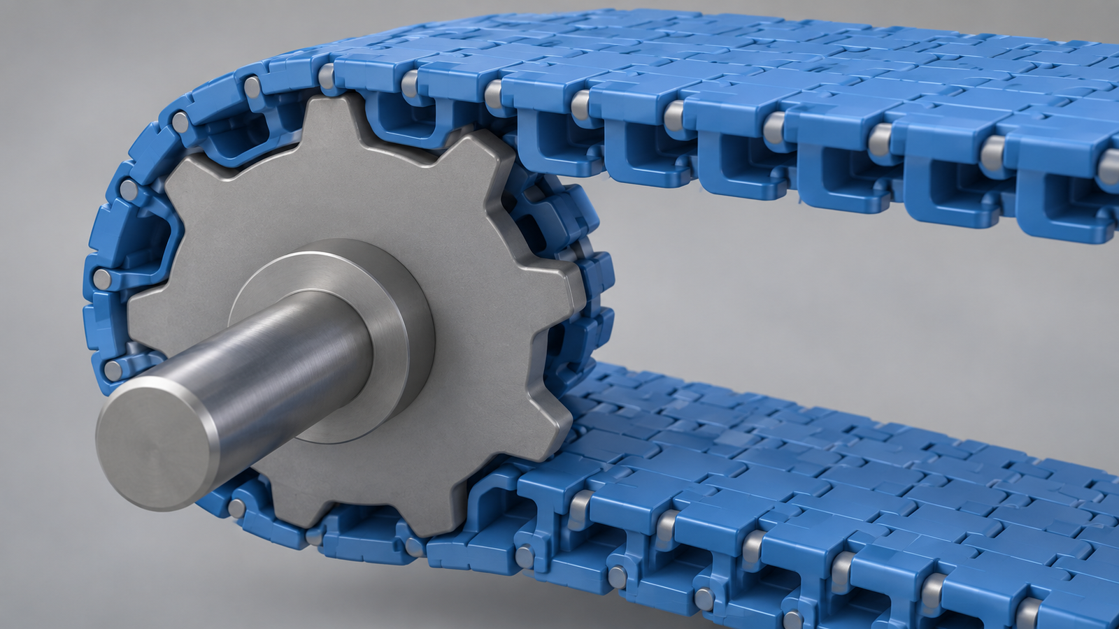
In a gear pair, tooth contact transfers motion directly between the gears. In a chain drive, the chain wraps around the sprocket and carries the force between the sprockets. A modular conveyor belt has its own drive features that engage the appropriate sprocket.
A belt-driven wheel is not automatically a conveyor sprocket. A flat-belt or V-belt pulley transfers force through friction against the belt. A timing-belt pulley uses teeth that match a timing belt. Identify the belt construction before choosing the part name or searching for a replacement.
Compare the Same Features
Mating Component and Force Transmission
The distinction concerns the contact arrangement, rather than whether a wheel is plastic or metal. Material alone cannot tell you which mechanism it belongs to.
| Feature | Gear Pair | Chain or Modular Belt Sprocket |
|---|---|---|
| Mating component | Another gear | The specified chain or modular belt |
| Contact that transmits force | Teeth on one gear contact teeth on the other | Sprocket teeth engage the chain or the belt’s drive features |
| What establishes the match | The documented tooth geometry and gear arrangement | The documented chain/belt series and its required sprocket geometry |
| Useful identification evidence | Gear markings, mating gear and assembly drawing | Sprocket markings, chain/belt identity and drive drawing |
These are different interfaces. A gear with a similar outside diameter and tooth count does not become a replacement for a sprocket. The tooth form still has to match the component it contacts.
Pitch, Tooth Count and Bore Answer Different Questions
Pitch describes the repeating engagement spacing. For a chain, it is the distance between adjacent joint centers; the sprocket must match that chain’s pitch and engagement form. A modular belt has its own row pitch and underside drive geometry. In a gear pair, the match concerns the spacing and profile of the gear teeth that mesh directly. A chain-pitch value cannot identify a mating gear or a modular-belt series.
Tooth count tells you how many engagement positions pass in one wheel revolution. Pitch diameter (PD) describes the reference pitch circle associated with that engagement; outside diameter (OD) measures the outer tooth envelope. They are different measurements. For a given chain or belt series, changing the tooth count changes the pitch diameter. The bore has a separate job: it fits the wheel to the shaft, with its specified shape, keyway and retention arrangement. Intralox’s Summer 2026 engineering manual, page 519, distinguishes these sprocket dimensions.
Two published CS sprocket rows show why neither tooth count nor bore is enough:
| Published Sprocket Code | Teeth | Pitch Diameter | Outside Diameter | Listed Bore Options |
|---|---|---|---|---|
| 1-1272-12T | 12 | 46.94 mm | 47.50 mm | 20 or 25 mm |
| 1-1500-12T | 12 | 57.96 mm | 58.2 mm | 20 or 25 mm |
These exact codes appear in the company product tables on the 1270 belt page and 1505 belt page. Both wheels have 12 teeth and the same listed bore choices, yet their pitch diameters differ. Selecting a 25 mm bore resolves only that nominal shaft dimension; it does not make the two tooth patterns interchangeable. Check the full sprocket code against the documented belt series and drive geometry.
How Pitch and Teeth Determine Chain Advance
In a matching chain drive, one sprocket revolution advances one chain pitch for each tooth. Rexnord’s 7010 Technical Data expresses average chain speed in metric units as:
S = T × P × N / 1000
Here, S is chain speed in m/min, T is sprocket tooth count, P is chain pitch in mm, and N is sprocket speed in rpm. For a hypothetical matching chain with 12.7 mm pitch, a 20-tooth sprocket at 60 rpm gives:
S = 20 × 12.7 × 60 / 1000 = 15.24 m/min
The calculation shows why a different tooth count changes chain speed even when the shaft speed stays the same. It is a chain-advance example, not a modular-belt or gear configuration. A gear pair transfers rotation through its mating teeth rather than advancing a chain by P at each engagement.
For a modular belt, sprocket size also changes the motion at the conveyor end. Intralox’s page 527 shows the hinge rising as it passes over a tooth and the module center returning toward the horizontal path. A smaller sprocket makes the same belt articulate more sharply, increasing this chordal movement. Thus a change chosen for shaft fit or end space can also change belt motion; use the selected belt family’s sprocket data to assess it.
Identification and Matching Information
Record the installed arrangement as well as the loose part. A close photograph of a wheel shows its teeth and bore, but an overall view shows whether those teeth meet another wheel, a chain or a belt. Take close measurements and photographs within the conveyor only under the equipment’s isolation and maintenance procedure.
For either a gear or a sprocket, preserve visible part numbers, maker markings and the existing drawing reference. Record tooth count and the shaft connection, including the bore shape, keyway or other retention feature. Those details help identify a part, but they do not independently establish its mating geometry.
For a sprocket, include the chain or belt reference. A worn wheel may have lost markings or no longer show its original tooth profile clearly; the mating component and equipment documents can resolve information that the wheel alone cannot provide.
Identify a Conveyor Chain or Modular Belt Sprocket
Start with the actual conveying element. A chain has articulated links; a modular plastic belt has connected module rows. Each family needs the sprocket intended for its series and drive geometry. Even within one family, a similar width or nominal pitch does not establish interchangeability.
Look for the contact features on the correct side of the conveying element. For example, the top-and-bottom inspection section of Intralox’s modular plastic belt manual identifies underside drive bars or pockets as features that engage sprocket teeth. This explains why a photograph of only the belt’s conveying surface can leave the drive interface unidentified. Use the drawing for the actual belt series to confirm it.
Next, record whether the existing sprocket is at the drive or idler position, its tooth count, bore and keyway details, and whether its body is one-piece or split. Include the hub and retaining arrangement in the photographs. A split body describes how the sprocket is assembled around the shaft; it does not identify the chain or belt series by itself.
Keep roller-chain sizing information with the roller-chain system it describes. An ANSI roller-chain designation cannot substitute for a flexible conveyor chain or modular belt series reference. Matching begins with the actual series and its documentation, then proceeds to the wheel and shaft details.
Request the Correct Conveyor Sprocket
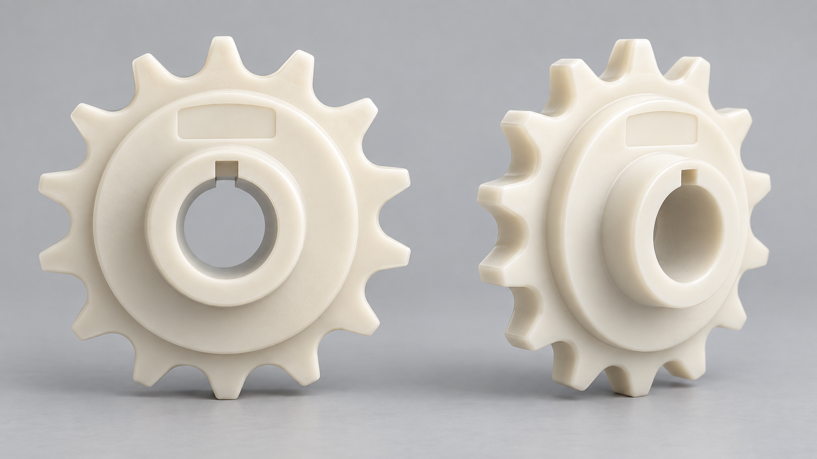
For a chain-driven conveyor, identify the conveyor chain together with the conveyor sprocket. For a modular belt, use the plastic modular belt sprocket range and provide the belt series reference.
Send the mating chain or belt identification, existing sprocket markings, tooth count, shaft-interface details, overall and close photographs, and quantity with your component request. State whether it is a like-for-like replacement or a proposed change. That gives the supplier a specific interface to check rather than a request for an unidentified toothed wheel.