
What Happens at a Dead Plate Conveyor Transfer?
A dead plate is a stationary surface between two conveying sections. It supports a product as the product leaves one moving surface and reaches the next, but the plate supplies no driving motion. The selection therefore has two separate questions: can the product remain supported through the junction, and what carries it across the passive surface?
The term “transfer” covers several constructions. A plain plate provides a continuous sliding surface. A comb plate has fingers arranged for a specified mating geometry. A roller transfer provides rotating contact surfaces, while a powered transfer uses a driven element to move the product through the junction. These parts do not become interchangeable because they occupy the same general location.
Dynamic Conveyor’s transfer overview describes a dead plate as a stationary bridge for products that can slide across it. That basic function helps identify the part; it does not establish suitability for every product or operating condition.
Compare the Product Base With the Junction
Bottom Shape and Support Continuity
Start with the part of the product that actually touches the conveyor. A container may be wide overall but stand on a narrow ring. A tray may rest on separate feet, while a carton presents a broader base. The outside length and width alone do not describe these contact footprints.
Follow those contact areas through the entire crossing. A foot can enter an opening even when most of the product remains over a plate. A recessed bottom may place its leading contact edge farther back than expected. A flexible package may deform into a discontinuity that a rigid base bridges. Product orientation matters because it changes which contacts reach the junction first.
Support must also be considered beneath the product’s weight distribution. As contact moves from the upstream belt to the plate and downstream belt, the supported area changes. A narrow base and a high center of gravity can respond differently from a low, broad product. This explains why two products with the same overall length can behave differently at the same junction; it does not predict a universal stable gap.
Inspect the plate’s leading and trailing edges as part of the support path. An edge projecting above the adjacent conveying surface can meet the product’s leading contact point. A damaged edge, raised fastener or accumulated residue may create a local obstruction that the overall plate dimensions do not reveal.
Gap, Height and Direction
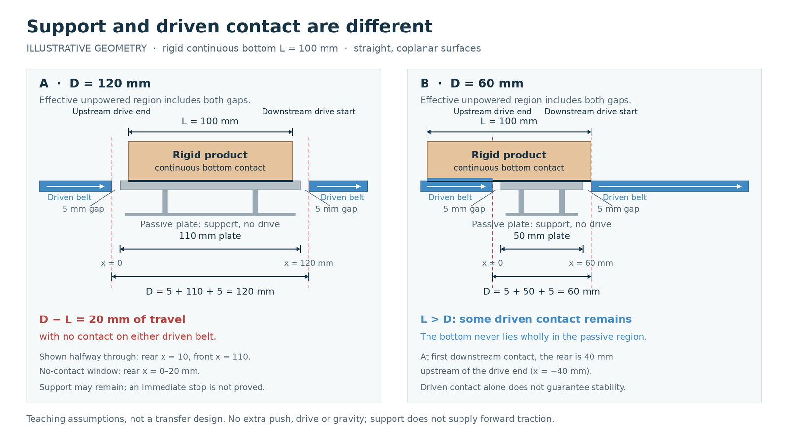
Record the junction as three interfaces: upstream belt to plate, across the plate, and plate to downstream belt. Distinguish an unsupported opening from a supported but non-driven surface. The effective non-driven distance D runs from the end of upstream driven contact to the beginning of downstream driven contact, so it includes entry gap + plate + exit gap. Plate length alone leaves out both local gaps.
Compare D with the product’s continuous bottom contact length L in the travel direction. For a recessed base or separated feet, overall package length is not L; the following simple comparison applies to a rigid, continuously contacting flat bottom.
Measure the surface heights at the actual entry and exit. An upward step presents an edge to the moving product; a downward step changes how its base lands and is supported. A plate that appears level from a distance may still differ from either moving surface at the contact point.
The local belt-to-plate gap can also change during motion. In Habasit’s April 2021 engineering guide, page 51, Fig. 550, its flat-top/flush-grid example places the discharge plate 1 mm below the belt surface and the infeed plate 1 mm above it. The guide explains that gap X5 varies as the belt moves: a hinge passing the edge changes the local geometry. Those maker-specific offsets illustrate why level and moving clearance are separate checks; they are not a setting for every CSTRANS transfer.
Record travel direction as well. For an angled or side transfer, the product does not simply cross the gap along its long dimension. Its leading corner, feet or base ring can encounter the interface in a different order. Reversible operation needs both directions assessed because the former exit edge becomes the entry edge.
There is no universal gap or speed threshold for these arrangements. Product contact geometry, stiffness, weight distribution, surface condition and motion all affect the crossing. Dimensions should be checked against the equipment documentation and assessed by the personnel responsible for the installation.
Separate Passive Support From Powered Movement
While part of the product remains on the upstream moving surface, that contact may supply the force needed to slide the rest over the plate. Once the product reaches the downstream moving surface, downstream contact can continue the motion. Between those stages, the amount and location of driven contact change.
A simple length comparison reveals when all direct belt contact can disappear. Assume a rigid, flat product with L = 100 mm, a straight coplanar transfer and no added pusher, drive or gravity assist. These are teaching dimensions, not recommended plate or gap sizes.
With D = 120 mm, made up of a 5 mm entry gap + 110 mm plate + 5 mm exit gap, the product fits wholly inside the non-driven region during part of the crossing. Once its rear leaves the upstream belt, its front is still 20 mm short of the downstream belt. Thus D − L = 20 mm of travel has no direct contact with either driven belt. The plate may still support the base, but it does not supply traction. The product might coast through that distance; the geometry alone does not prove an immediate stop.
With D = 60 mm, made up of 5 + 50 + 5 mm, the 100 mm bottom cannot fit wholly within the non-driven region. When its front first reaches the downstream belt, its rear remains 40 mm upstream of the upstream contact boundary. Some driven-belt contact persists through the crossing. This removes the all-contact-lost interval in this simplified geometry, but does not establish enough traction or stable support: contact load, friction, product stiffness and the height transitions still matter.
Following products may also supply pushing force. A trailing item could move one product across while an isolated item stops at the same location, so a successful crossing in a packed stream does not establish the behavior of separated products. Product-to-product pushing introduces forces that may be unsuitable for the package.
The friction between the product base and plate influences how much force is needed to move it. A coating, moisture or residue can change that contact. Motion also depends on the adjacent conveying speeds: unequal speeds can change the product’s movement as it contacts both surfaces. Replacing a plate does not independently resolve an unsuitable motion arrangement.
Rollers change the contact from sliding on a stationary face to contact with rotating elements; their diameter and spacing still affect support. Some rollers are passive and some are driven. A powered transfer adds a driven surface or mechanism through the junction, which also introduces drive and interface requirements. Span Tech’s transfer comparison distinguishes non-powered rollers from its powered compact transfer equipment. It is a useful mechanism distinction, not a specification for other suppliers’ parts.
Removing a dead plate also changes the junction. Intralox’s canmaking example concerns its specified tight-transfer belts and nosebar arrangement, including precise alignment and spacing. That example should not be read as evidence that simply taking out an existing plate creates a suitable direct transfer.
Identify the Existing Plate and Mating Interface
Identify the component before looking for a replacement by width alone:
| Visible construction | Interface to identify | What appearance does not prove |
|---|---|---|
| Plain stationary plate | Edge profile, thickness, mounting, surface position and clearances to moving parts | Suitability for the product base or enough force to cross it |
| Comb or finger plate | Finger pitch and geometry, mounting and the specified mating belt arrangement | Engagement with any belt that has visible ribs or grooves |
| Roller unit | Roller diameter and spacing, frame mounting, support height and whether it is driven | Continuous support for small feet or compatibility with another frame |
| Powered transfer | Moving element, drive arrangement, conveying direction and connections to adjacent equipment | A drop-in replacement for a passive plate |
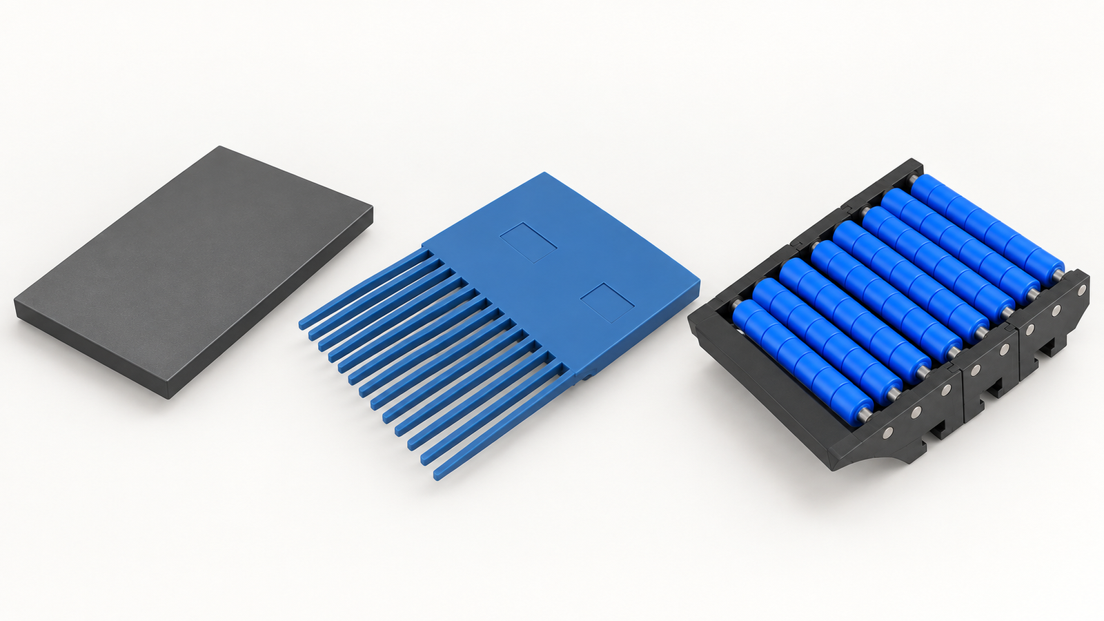
For a comb, preserve the belt or chain series identification and the actual finger arrangement. The CSTRANS transfer plate range lists 5712 plates with 12 teeth and 146 or 220 mm lengths, and 5713 plates with 28 teeth and 147 or 220 mm lengths. Both include a 220 mm option, but that shared length does not make their tooth pattern or mating interface the same. A photograph showing fingers beside a belt is likewise not proof of correct engagement. For a plain plate, record how it is secured and which clearances prevent contact with the moving belt or chain. The mounting arrangement must hold the intended position without treating a similar outer shape as an interface match.
Use the site’s isolation and maintenance procedure before close inspection, measurement or removal. Record damaged or displaced parts as found, but distinguish that condition from the intended drawing or setup. Any change to plate position, conveying direction or drive arrangement requires assessment by the personnel responsible for the equipment.
Prepare a Transfer Plate Parts Request
For a conveyor transfer plate request, send the existing part identification, photographs of both interfaces, measured gaps and surface heights, mounting details and quantity. Include the product’s actual bottom contact shape and travel direction. If the junction belongs to a flexible-chain arrangement, identify the corresponding flexible chain transfer component and chain series. Use the component request form to have the mating parts and supply scope checked.