
83 Machined Flexible Chain Sprocket
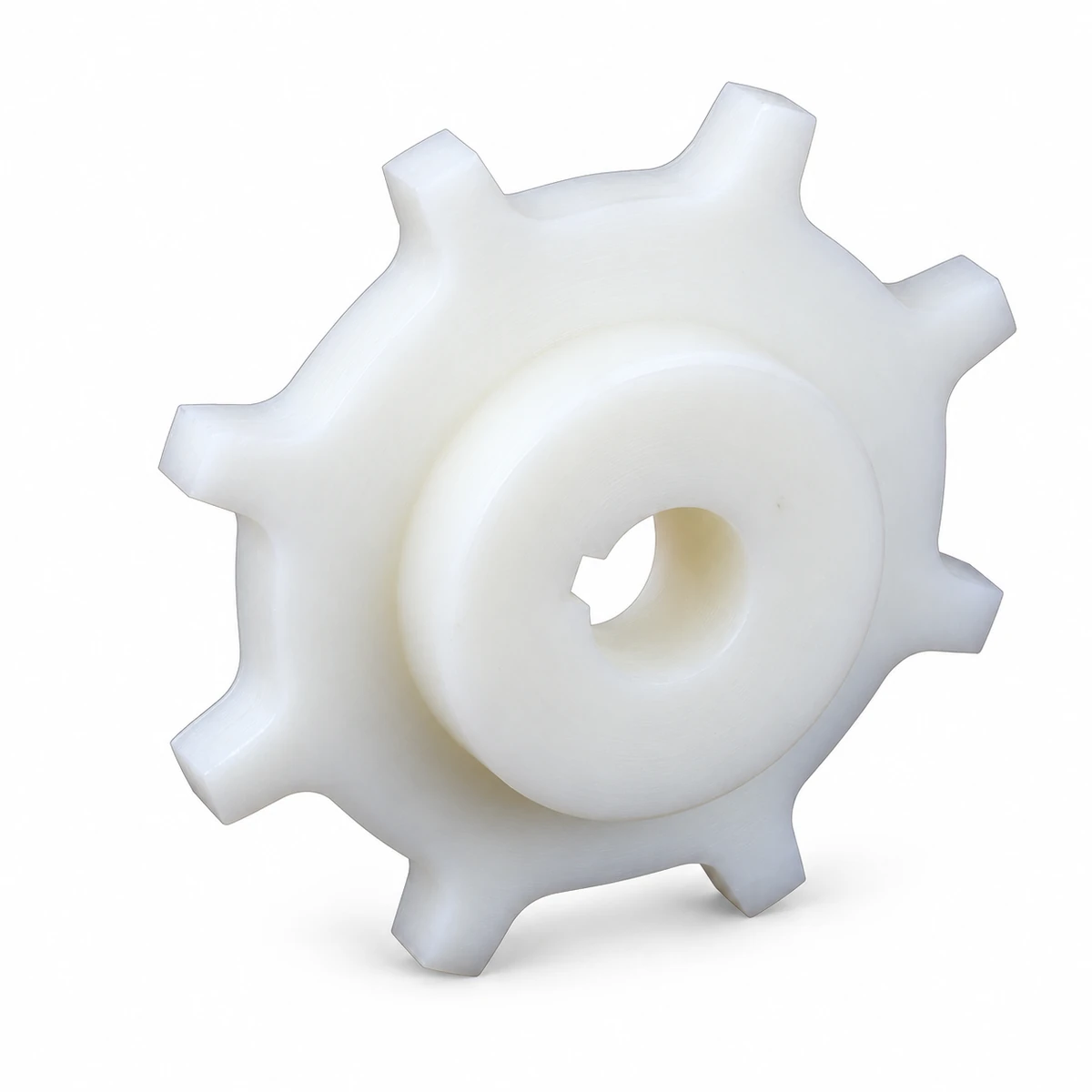
The 83 machined sprocket engages the flexible chain at the drive end. Two tooth counts provide different wheel diameters, so tooth selection affects the space around the chain as it turns around the shaft.
- Family
- 83
- Tooth Counts
- 9 / 12
- Material Options
- PA / PP
Choose the Tooth Count Before Checking End Clearance
Compare the chain path around the wheel with the available end-unit space and shaft position.

Tooth Engagement at the Drive End
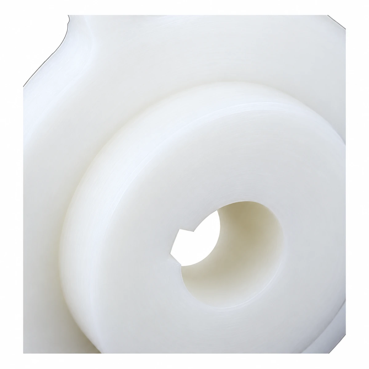
Sprocket teeth engage the chain beneath the carrying surface and transmit rotation from the shaft. Correct engagement depends on the chain geometry as well as tooth count. A wheel with a similar outside diameter can still have the wrong tooth profile.
The 9-tooth option has the smaller envelope. The 12-tooth option carries the chain around a larger wheel. Check the shaft location, surrounding guards and chain return together when selecting between them.
Specifications
| Item | Teeth | Bore Range (mm) | Pitch Diameter (mm) | Outside Diameter (mm) |
|---|---|---|---|---|
| 1-83-T9 | Teeth: 9 | Bore Range (mm): 20–40 | Pitch Diameter (mm): 97.95 | Outside Diameter (mm): 100 |
| 1-83-T12 | Teeth: 12 | Bore Range (mm): 20–50 | Pitch Diameter (mm): 129.46 | Outside Diameter (mm): 135 |
Machined material options are PA and PP. Round and square bore options are listed. Specify the finished bore shape and shaft dimensions with the order.
Idler Wheel Reference
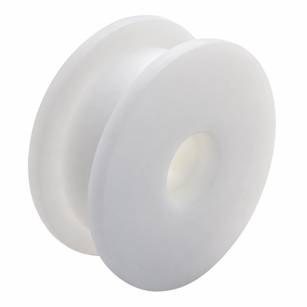
The 2-83-T12 is a separate machined idler reference for the unpowered return end. Its 15 mm bore and wheel dimensions differ from the drive options above. Confirm the actual chain engagement and axle arrangement for this reference before ordering.
Machined Idler Wheel Sizes
| Item | Number of teeth | Bore (mm) | Pitch diameter (mm) | Outside diameter (mm) | Forming method |
|---|---|---|---|---|---|
| 2-83-T12 | Number of teeth: 12 | Bore (mm): 15 | Pitch diameter (mm): 129.4 | Outside diameter (mm): 138.5 | Forming method: Machined |
Resolve the Shaft Connection
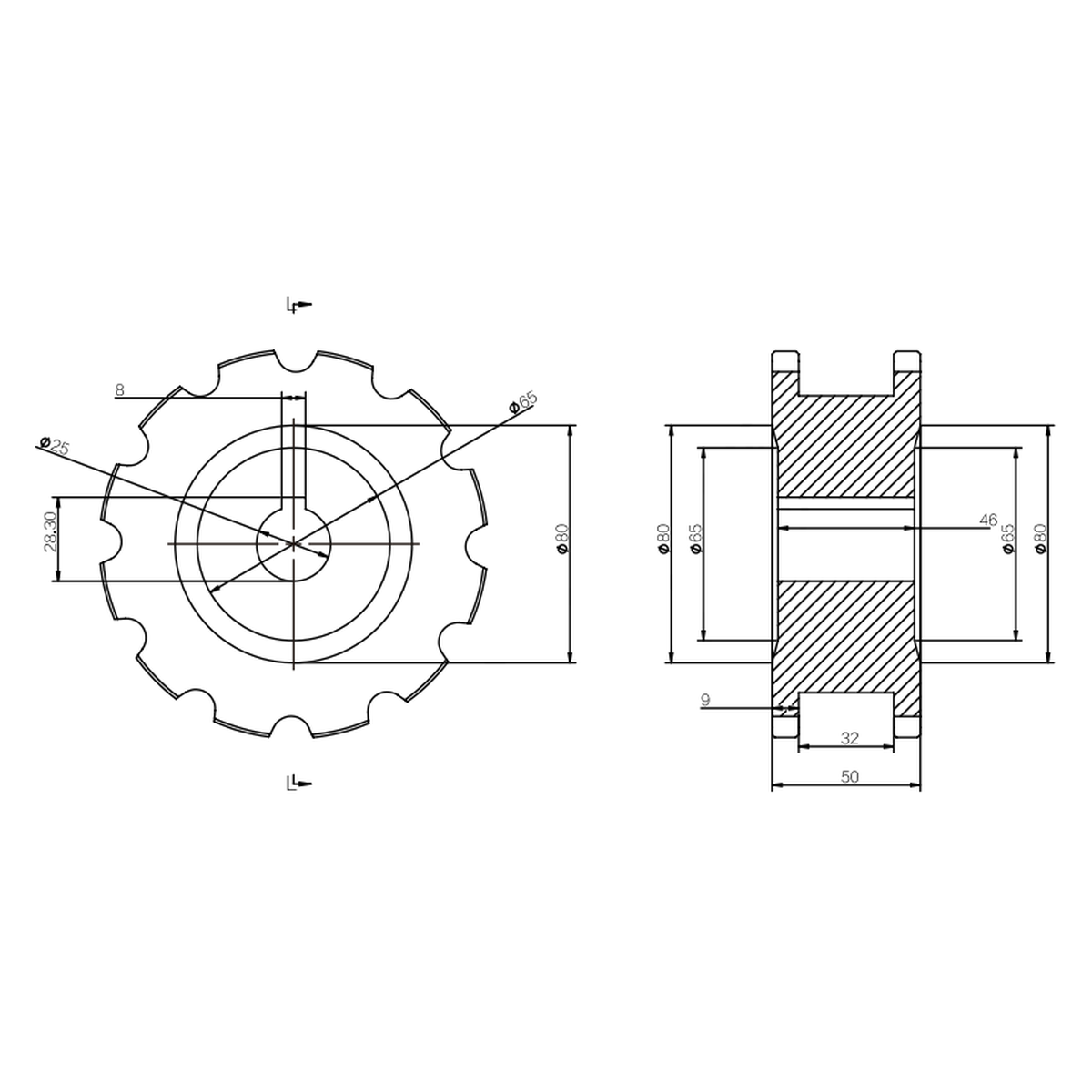
For a round shaft, show the bore, torque-transmission features and axial retention arrangement on the drawing. For a square shaft, provide the across-flats dimension and corner detail. The listed bore range does not define those features by itself.
Check the wheel's axial position against the chain track. Leave room for the chain to enter and leave engagement without rubbing the end structure.
Renewing the Chain Drive
A replacement sprocket must seat the chain correctly as each link reaches the wheel. Inspect the existing chain and tooth contact together; wear at either can change engagement.
On a new end assembly, the chosen wheel diameter establishes part of the chain's turning path. The enclosure and product-transfer arrangement must accommodate that path before the shaft position is fixed.
Request the Required 83 Sprocket
Send the tooth count, material preference, finished shaft drawing and quantity. Include the chain reference and end-unit drawing for CSTRANS to compare engagement and clearance.