
305 Square Bipod Conveyor Support Base
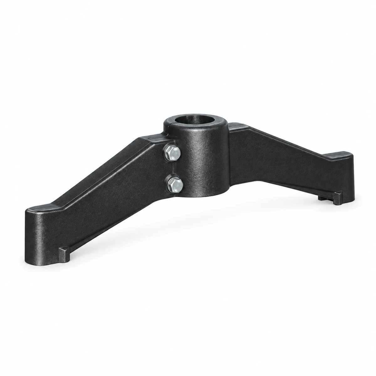
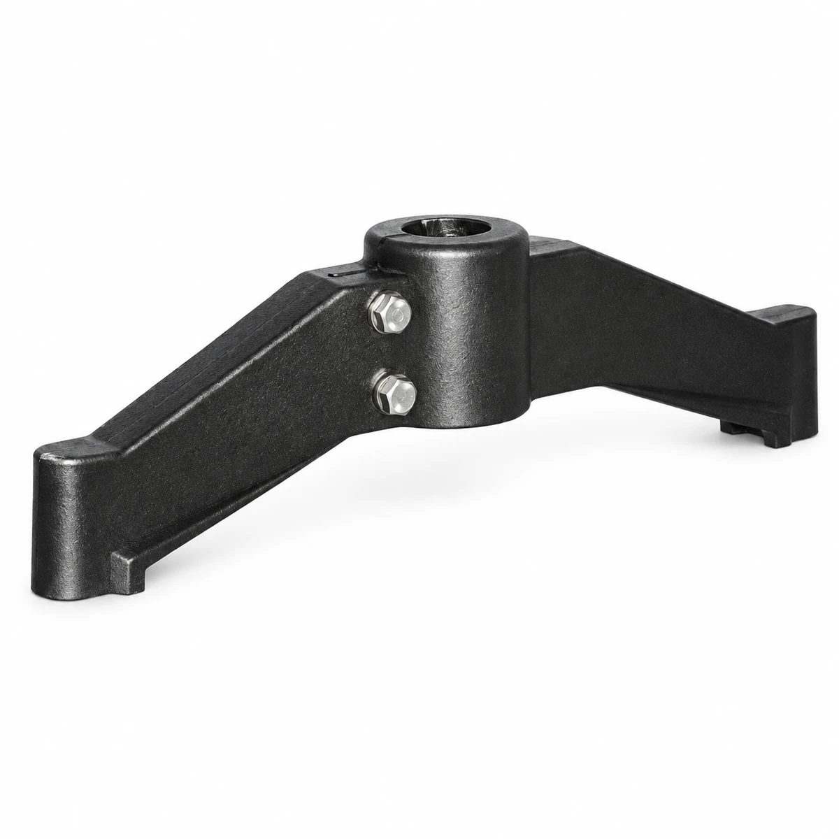
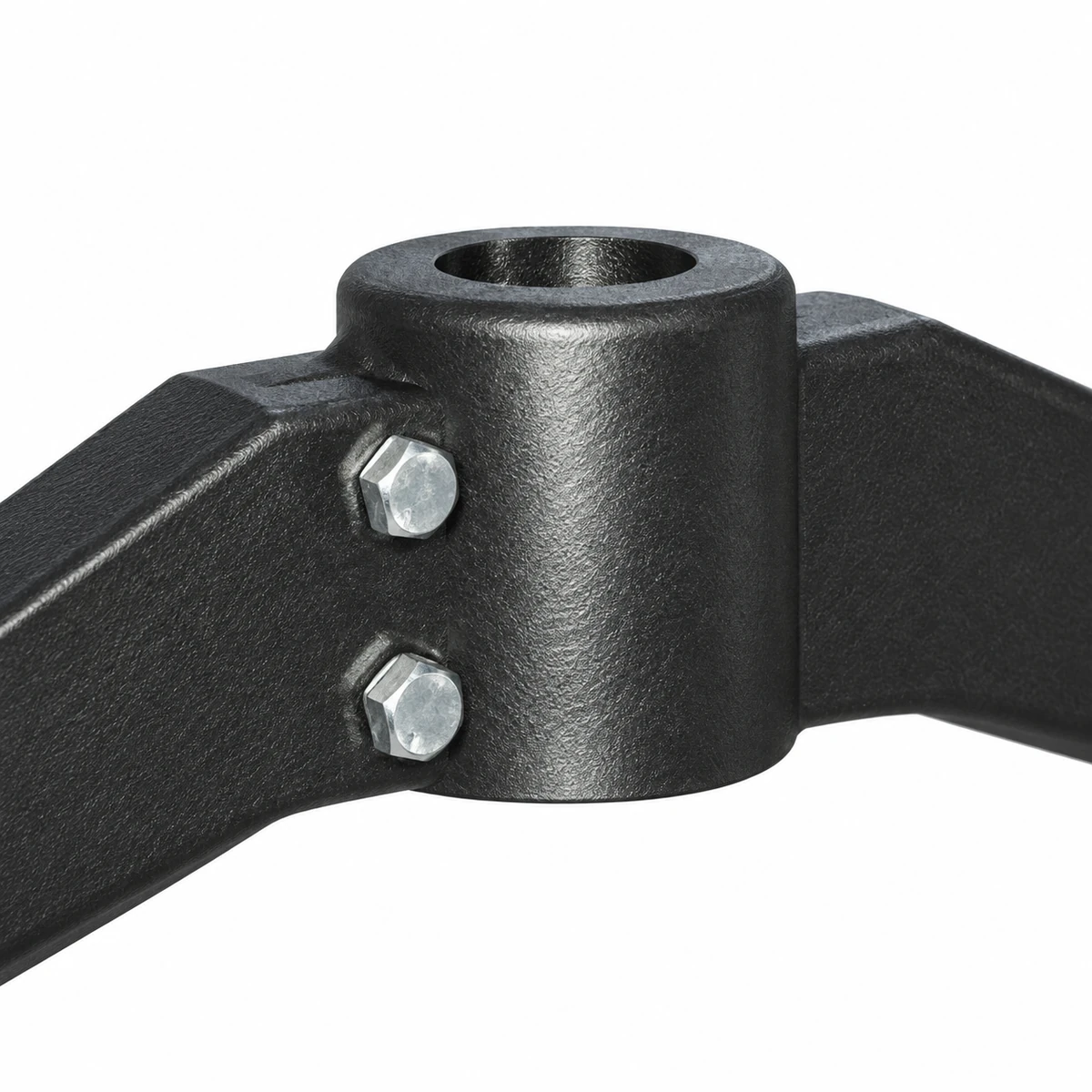
The 305 support base holds a conveyor upright between two projecting support arms. The central clamping body locates the upright, while threaded connections at the arm ends accept leveling feet.
- Code
- 305
- Support Layout
- Two arms
- Foot Connection
- M16
Match the Central Opening to the Upright
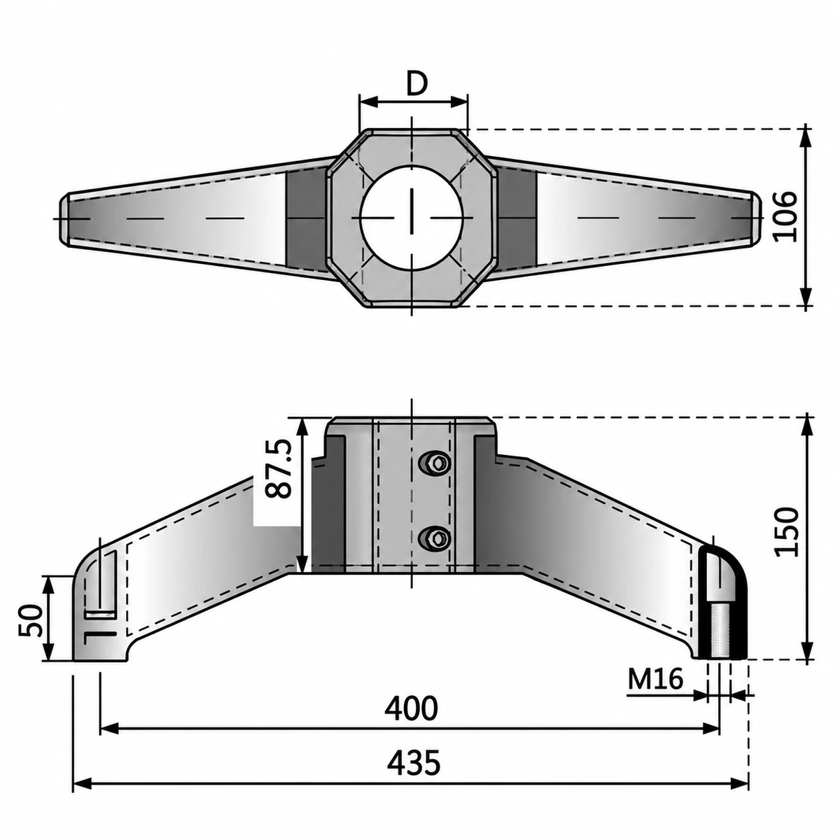
Use the opening profile and clamping arrangement in the drawing to check the post; the product name alone does not establish post shape.
Connect the Upright to Two Floor Contact Points
The central body clamps around the vertical support member. Its two arms spread the floor contact positions away from the upright. Leveling feet connect at the ends so the supported frame can be set to the required height and level.
The base is one part of the conveyor support structure. Upright height, frame loading and the direction of horizontal forces determine how it should be positioned and braced. A two-arm footprint needs review with the neighbouring supports.
Specifications
| Parameter | Specification |
|---|---|
| Code | Specification: 305 |
| Construction | Specification: Bipod support base |
| Materials listed | Specification: Reinforced polyamide / zinc-plated steel |
| Foot connection | Specification: M16 |
| Central opening | Specification: Select to match the upright drawing |
Check the Footprint Below the Conveyor
Compare the arm span and height in the drawing with floor space and the required leveling-foot position. Check thread engagement at each end and the remaining height adjustment after installation.
Measure the upright's outside dimensions and show its cross-section. Confirm how the clamp engages it before selecting the opening. Keep the support clear of access routes and review stability against the complete frame load.
Support a Conveyor Frame Along Its Length
A bipod base provides two local floor contacts beneath an upright. Along a straight conveyor, several supported uprights share the frame load. Their spacing and connection to the frame govern the overall support arrangement.
At a bend or an offset frame, horizontal loading may act across the two-arm footprint. Check the base orientation and any bracing as part of the structural layout before fixing the foot positions.
Check a 305 Base for Your Upright
Send the upright cross-section and dimensions, required base quantity and leveling-foot reference. Include frame height and the support layout for CSTRANS to review the fit.