
810 Rubber Chain Return Roller
The 810 return roller supports the underside of a conveyor's returning chain or belt. Its ribbed cylindrical running surface and 20 mm bore make the contact position and shaft arrangement the first checks for replacement.
- Model
- 810
- Bore
- 20 mm / 0.7874 in
- Duty
- Chain or belt return support
Check the Returning Surface
Position the roller so the returning chain or belt contacts the running surface without rubbing adjacent guides or mounting brackets.
Support the Chain on Its Return Run
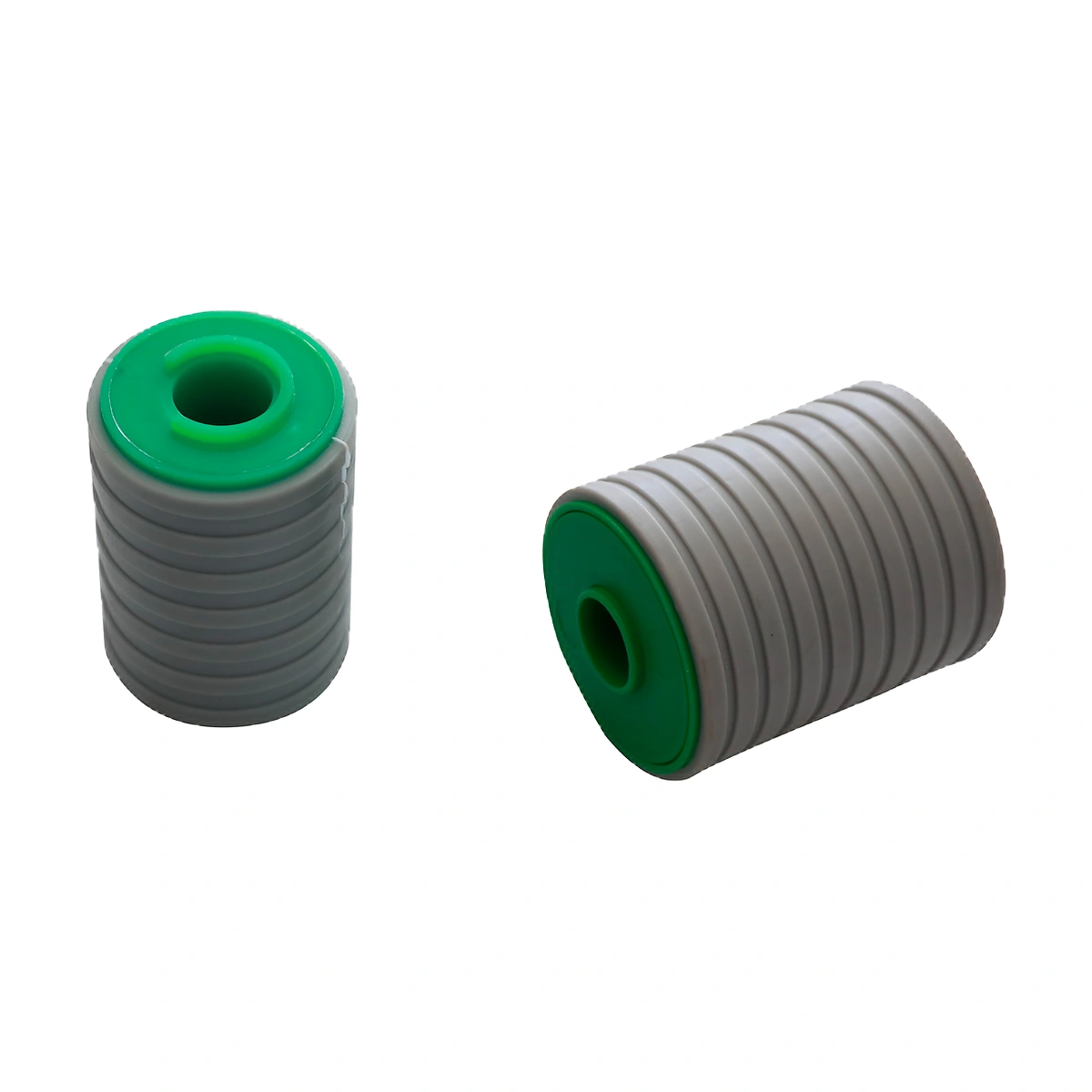
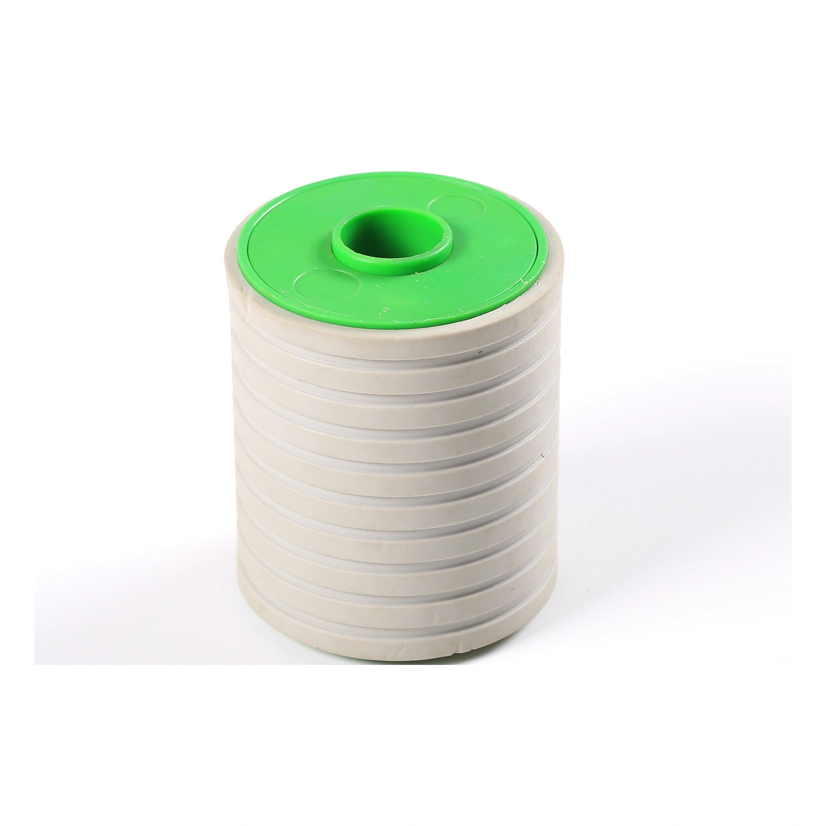
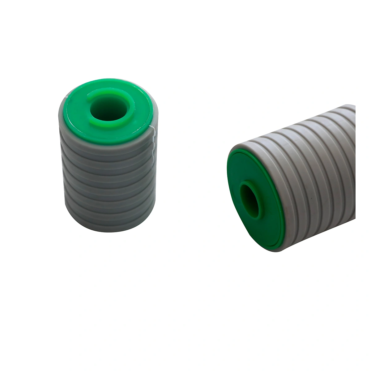
The return run needs support after the chain or belt leaves the carrying side of the conveyor. The 810 provides a rotating contact surface at that support point. Its circumferential ribs are visible across the roller body, while the central bore locates it on the supporting shaft.
Roller position affects how the underside passes through the frame. Check which part of the chain makes contact, especially where hinges, tabs or projecting features pass the roller. A bore match alone does not establish clearance through the return route.
Specifications
| Parameter | Specification |
|---|---|
| Model | Specification: 810 |
| Bore diameter | Specification: 20 mm / 0.7874 in |
| Component type | Specification: Return roller |
| Running surface | Specification: Circumferentially ribbed |
Check Shaft Space and Contact Position
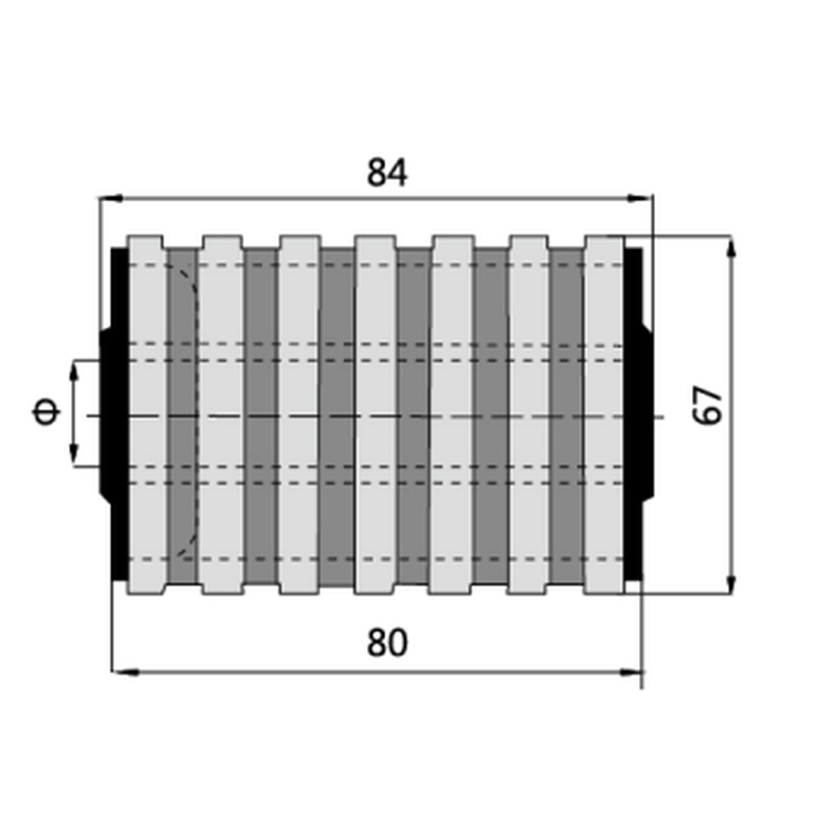
Compare the roller drawing with the shaft's usable length and the space between brackets. Establish the required running clearance and axial retention before ordering. The roller must turn freely after the mounting hardware is secured.
Show the underside of the existing chain or belt and its path around the return supports. Include roller spacing and operating speed when checking the support arrangement. Material selection should be agreed for the actual operating and cleaning conditions.
Return Support Below the Carrying Surface
On a chain conveyor, the unloaded return strand travels below the product-carrying level. Rollers provide local support along that route and can keep the strand clear of the lower frame. At transitions between supported and hanging sections, the approach angle determines how the chain meets the roller.
For a modular belt, check the underside features and available support width before choosing the contact position. The roller layout must accommodate the returning belt throughout its travel, including changes near the drive and idler ends.
Request an 810 Roller Quote
Send the roller quantity, shaft details and a photograph of the existing return arrangement. Include the chain or belt reference and operating conditions so CSTRANS can review the required configuration.