
Bipod and Tripod Conveyor Support Bases
Codes 301–304 provide two-arm, jointed and three-arm bases for conveyor uprights. Choose the floor-contact layout around the frame load and available space, then match the central clamp to the support post.
- Range
- 301–304
- Jointed Layouts
- 120° / 180°
- Materials Listed
- Reinforced polyamide / zinc-plated steel
Choose the Floor Layout First
Check where each leveling foot will contact the floor and how that footprint supports the upright under the actual load.
Arrange Support Around the Conveyor
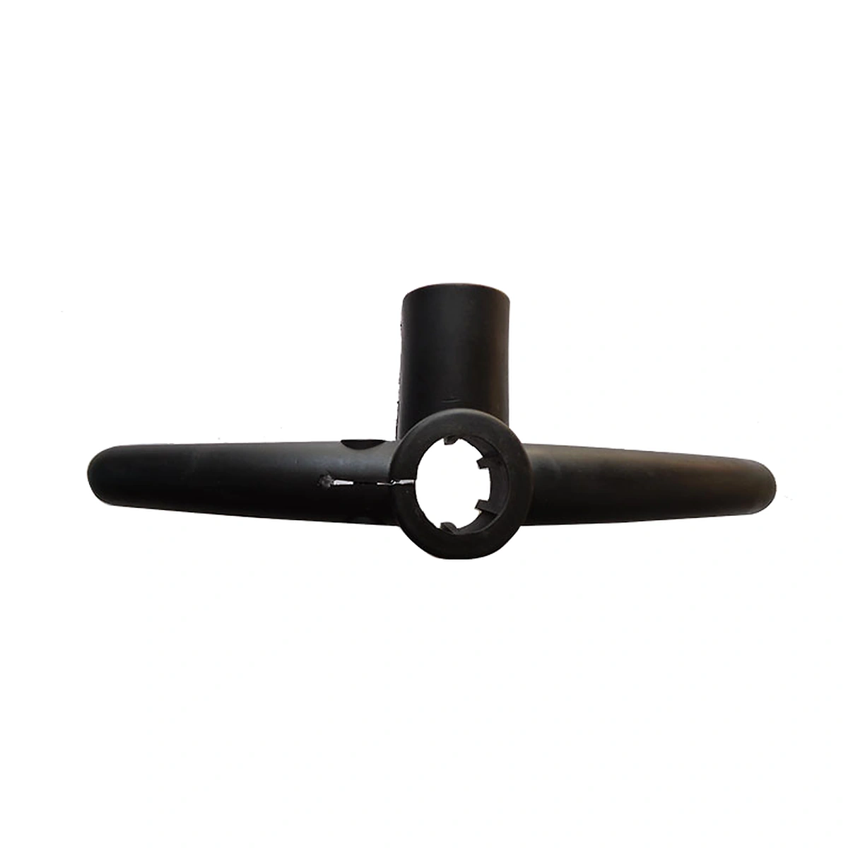
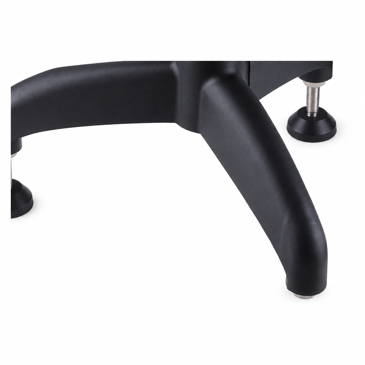
A bipod places two contact points beneath an upright; a tripod spreads them across three arms. The jointed 302 and 303 arrangements offer different arm directions. These differences matter where a conveyor bend, wall or adjacent machine limits the available floor space.
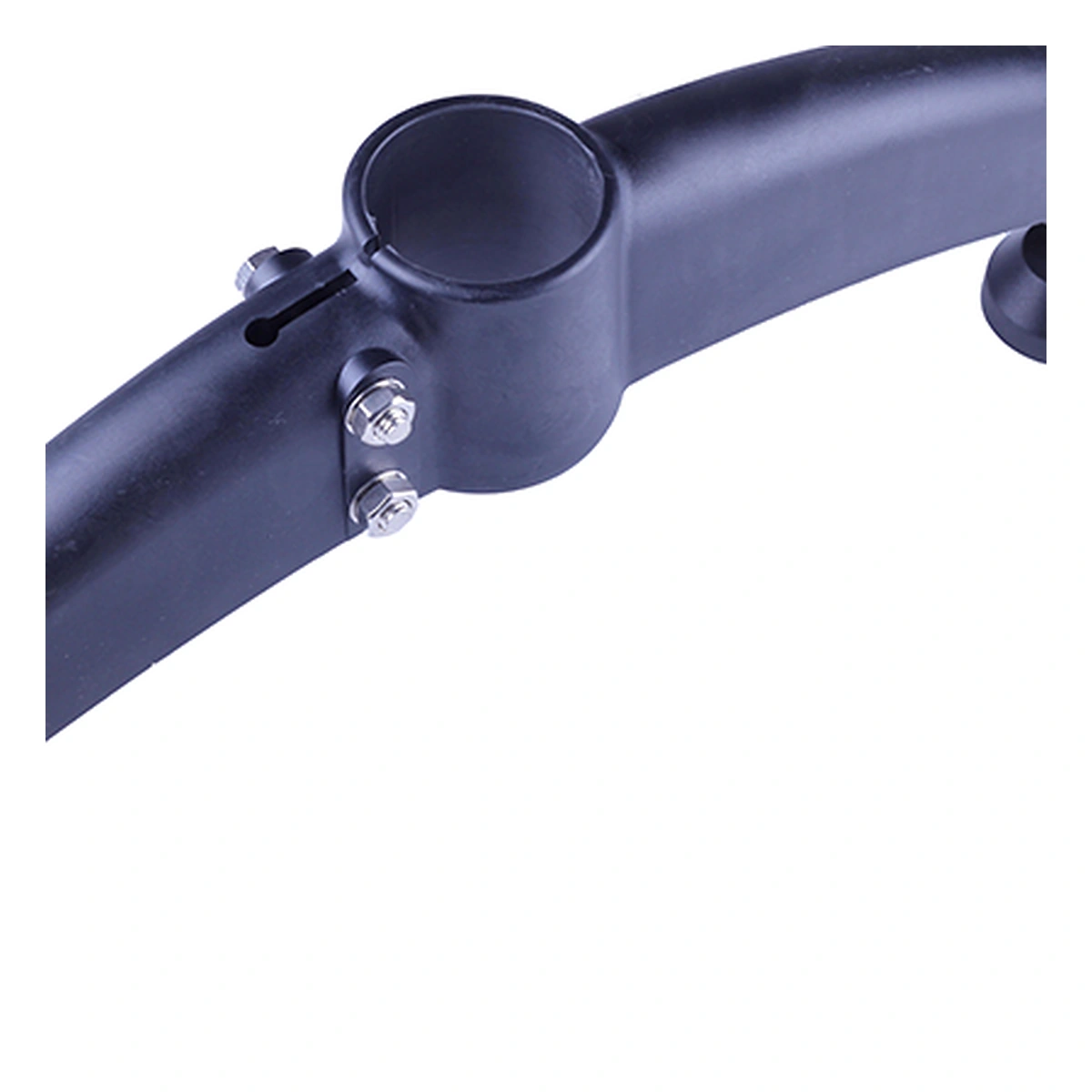
The central clamp connects the base to the post. Leveling feet beneath the arms set the contact height. Their positions should support the expected load without forcing a foot into an aisle or leaving insufficient adjustment beneath the frame.
Specifications
| Code | Base Arrangement | Joint Angle |
|---|---|---|
| 301 | Base Arrangement: Bipod | Joint Angle: Fixed two-arm layout |
| 302 | Base Arrangement: Jointed bipod | Joint Angle: 120° |
| 303 | Base Arrangement: Jointed bipod | Joint Angle: 180° |
| 304 | Base Arrangement: Tripod | Joint Angle: Three-arm layout |
| Parameter | Specification |
|---|---|
| Materials listed | Specification: Reinforced polyamide / zinc-plated steel |
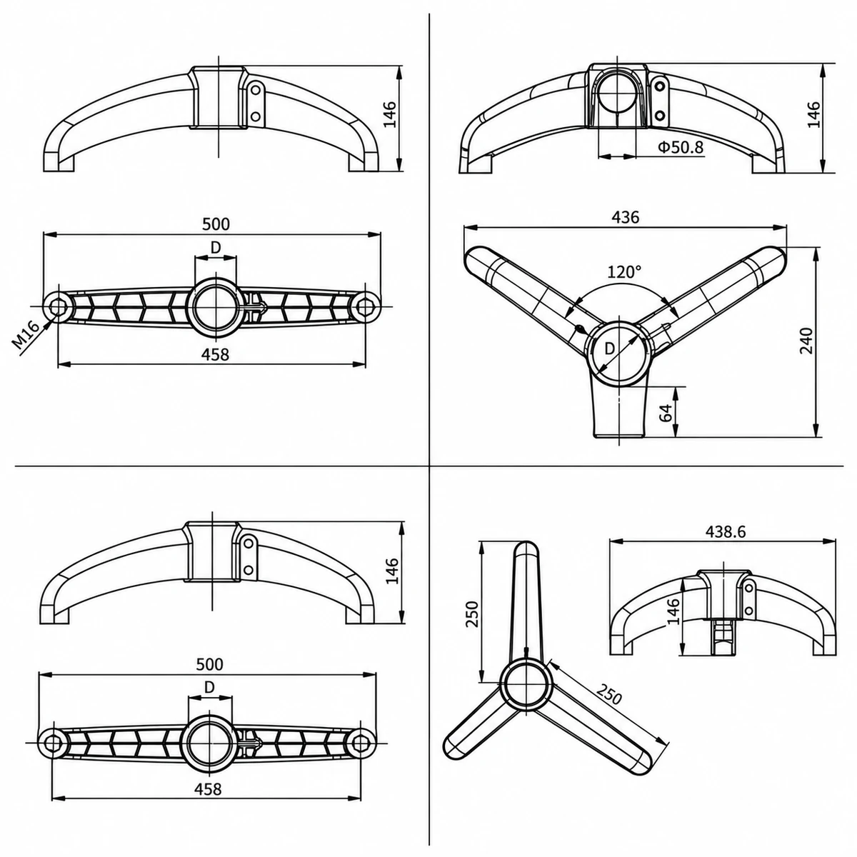
| 301 foot thread shown | Specification: M16 |
| Upright opening | Specification: Select for the measured post and base code |
Review Each Base in Plan and Elevation
Use the drawing for the selected code to check arm direction, foot positions and the height of the central body. Compare the post section and outside diameter with the clamping opening. Confirm the foot thread for the chosen assembly.
Check the support layout under the complete conveyor. Base count, upright height and bracing determine how vertical and horizontal forces reach the floor. Establish the required leveling travel before selecting foot stems.
Support Straight Runs and Constrained Corners
Opposing arms can suit a straight section where floor space is available across the frame. An angled or three-arm layout changes the contact footprint where a bend or equipment edge occupies part of that space.
These layouts require a structural check with the actual frame. A wider-looking base does not establish its load capacity, and the leveling feet must remain seated as the conveyor is brought level.
Plan Your Support Base Arrangement
Send the preferred code, post dimensions and quantity, together with a floor-layout sketch. Include frame height, expected loading and the proposed leveling feet.