
64×64/80×80 Conveyor Frame Profile
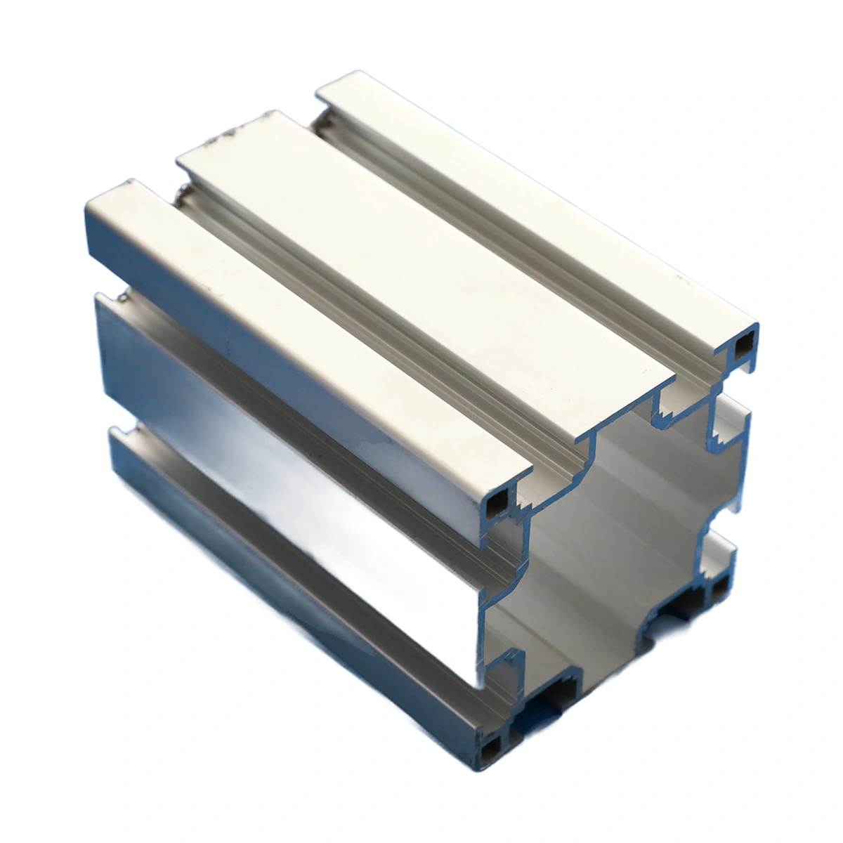
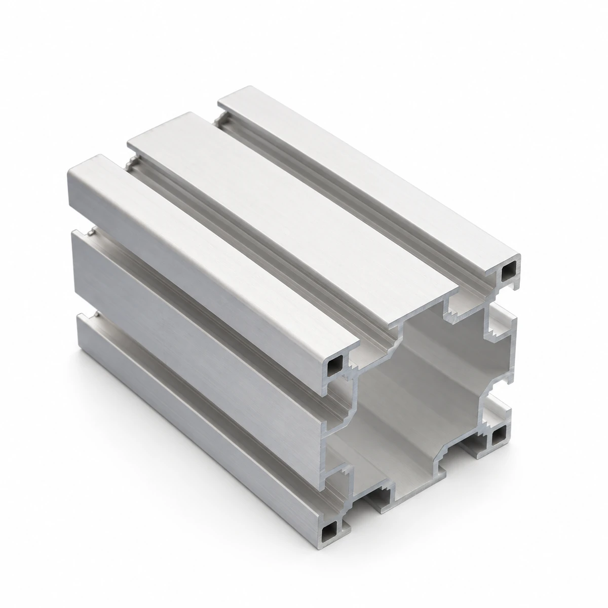
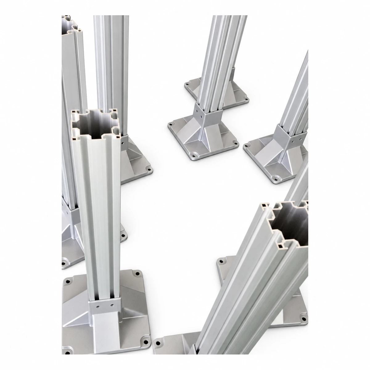
The 64×64/80×80 conveyor frame profile range provides upright support members used with base feet. Choose the section together with the foot connection and the conveyor support arrangement.
- Designations
- 64×64 / 80×80
- Role
- Upright support
- Base connection
- Matched foot
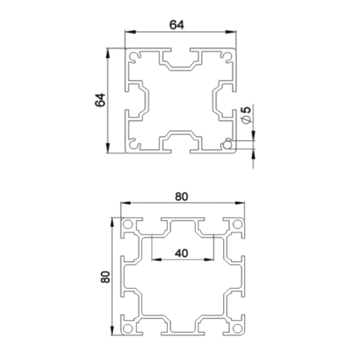
Compare the end section and foot attachment. The two designations identify different profiles, not interchangeable base connections.
Carry the Conveyor From an Upright Support
The upright links the beam-support structure to the base foot. Its joint positions establish the conveyor elevation and the location of the surrounding cross members. The selected profile needs to work with those connections as one frame assembly.
64×64 and 80×80 are separate section choices. Compare the end geometry, fastening faces and available foot attachment before choosing a replacement. A larger designation alone does not establish the permissible support load.
Specifications
| Parameter | Specification |
|---|---|
| Profile choices | Specification: 64×64 / 80×80 |
| Use | Specification: Upright support |
| Associated component | Specification: Base foot |
Dimensions & Fit
Show the upright height and the positions of the crossbeam and conveyor-support joints. Include the actual section end view and base-foot interface.
Check the space needed for foot adjustment and fixing access. Review the load and frame stability with the chosen support spacing rather than selecting the upright by section designation alone.
Establish Conveyor Height Above the Floor
Upright profiles set the position of the conveyor relative to adjoining equipment. The base foot provides the floor connection, while the upper support holds the beam at the required height.
On an uneven floor, consider the foot's available adjustment within the complete support design. Check that the frame remains aligned when the conveyor elevation is set.
Discuss an Upright Profile
Send the 64×64 or 80×80 reference, upright lengths and quantity. Include section/end photographs, base-foot details and the support layout.