
63 90 Degree Wheel Bend
The 63 90 degree wheel bend changes the conveyor direction through a right angle using a plastic wheel assembly. It is selected as part of the 63-series chain route.
- Series
- 63
- Direction change
- 90°
- Mechanism
- Wheel bend
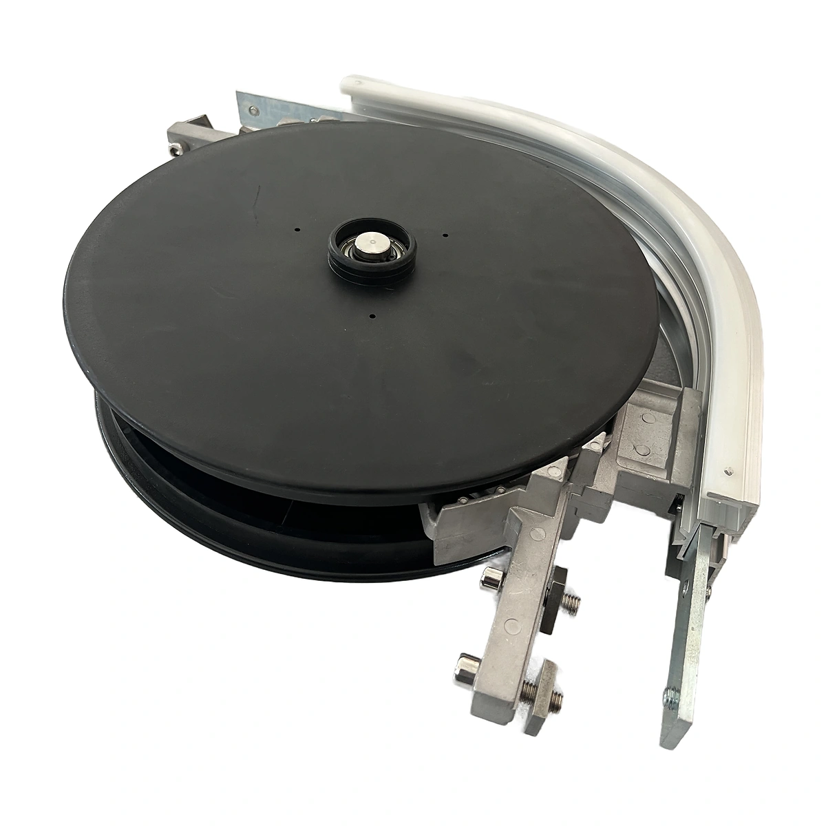
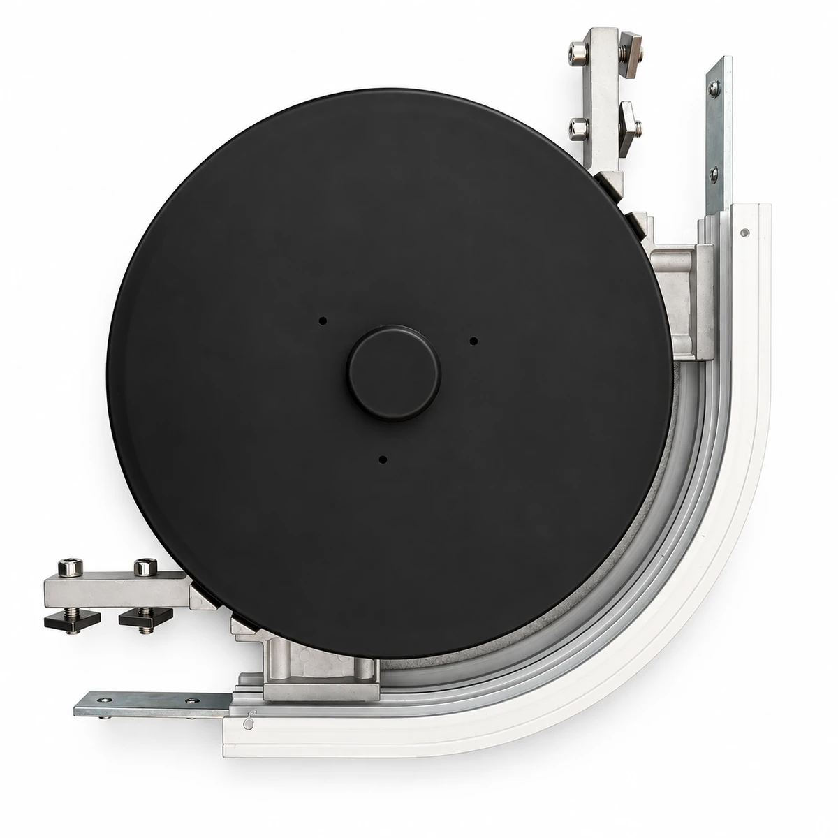
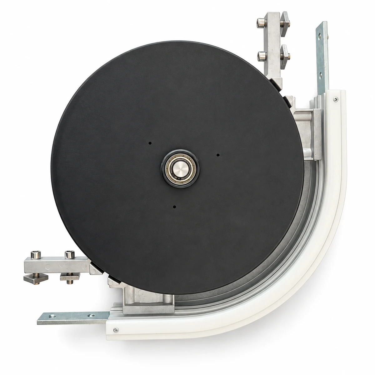
Check the complete right-angle assembly, including both beam connections. The wheel and curved beam need to locate the chain on the same path.
Make a Right-Angle Route Change
The wheel guides the chain around the inside of a 90° turn. The photographed assembly includes a large dark disk beside the curved profile and projecting connection pieces at the beam ends.
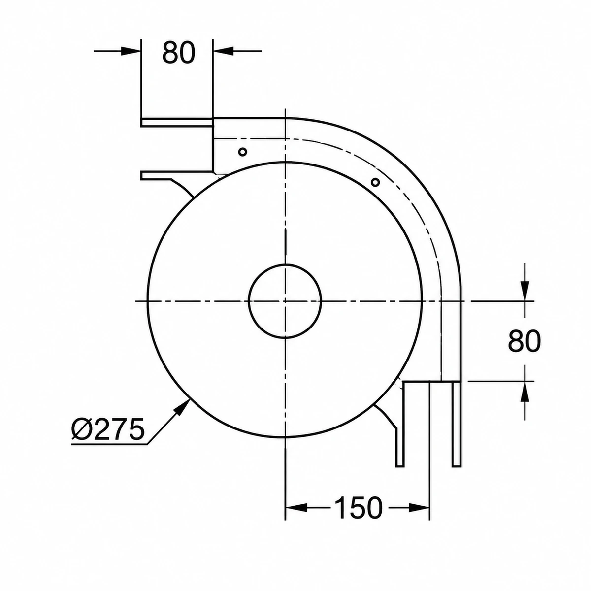
A right-angle turn fixes the direction of the outgoing conveyor, but its footprint also depends on the chosen radius and tangent lengths. Compare the complete assembly with the planned machine spacing before positioning the straight runs.
Specifications
| Parameter | Specification |
|---|---|
| Chain family | Specification: 63 |
| Bend angle | Specification: 90° |
| Type | Specification: Horizontal wheel bend |
| Assembly elements | Specification: Plastic disk, bracket, half beam and shaft |
Dimensions & Fit
Provide both straight-run directions and the required chain-path position. Check the centre support, end connections and the space available inside the bend.
Confirm clearance for products that overhang the chain. A rectangular item sweeps extra space at its corners while changing direction.
Carry Products Around a Corner
The 90° bend can link conveyor runs arranged at right angles. The chain changes direction around the wheel while the product guides define the usable lane above it.
At entry and exit, keep the carrying level and guide position consistent. Assess narrow bases and long packs separately because they follow different support and swept-clearance conditions.
Request a 63 Wheel-Bend Quote
Send the 63 chain reference, right-angle layout and required footprint. Include the existing wheel assembly photograph and quantity.