
What Is a Pillow Block?
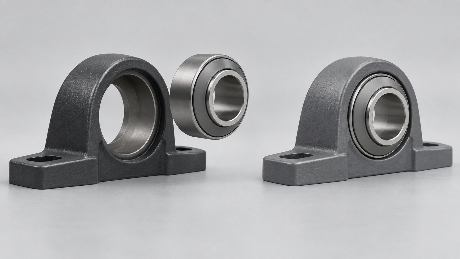
A pillow block is a shaft-support arrangement with a bearing held in a housing that mounts through a base. The housing stays attached to the equipment while the bearing supports the rotating shaft. In parts descriptions, “pillow block” may refer to the assembled bearing unit or to its housing form, so the name alone does not tell you what is included in an order.
LDK’s definition describes the stationary housing and the bearing supporting the shaft. To identify a replacement, separate that assembly into its parts: the housing provides the seat and mounting interface; the bearing provides the interface with the shaft. Requesting a housing is therefore a narrower request than asking for a complete pillow block bearing unit.
Bearing, Housing and Complete Unit: How the Parts Relate
The Housing and Its Mounting Base
The pillow-block form has a bearing seat above a mounting base. The base’s holes or slots provide attachment to the supporting surface. Its height and mounting geometry determine where the shaft is supported relative to that surface. ASKUBAL’s pillow block knowledge base describes this base-mounted housing form.
“Bearing housing” is a broader term. ASKUBAL’s bearing-unit guide also shows flanged, take-up and cartridge forms. These have different mounting arrangements; calling all of them pillow blocks would hide the interface needed for a replacement.
Identify the shape and mounting arrangement of the housing you actually have. A photograph of only the bearing opening omits the base or flange that distinguishes the housing form. The housing’s outline also cannot tell you which bearing is fitted inside it.
Four dimensions explain why the shaft size alone cannot identify a replacement. The SNR product listings for UCP205 and UCP305 provide a concrete comparison. SNR lists UCP205 as a kit containing the UC205G2 insert and P205 housing, and UCP305 as a kit containing UC305G2 and P305. These are complete-unit examples: the shaft dimension belongs to the insert, while the mounting dimensions describe the housing.
| Dimension | What It Locates | SNR UCP205 | SNR UCP305 |
|---|---|---|---|
| d — shaft diameter | The nominal shaft size received by the insert bore | 25 mm | 25 mm |
| H — mounting base to seating centerline | The nominal shaft-center height above the mounting surface in the assembled unit | 36.5 mm | 45 mm |
| J — mounting-hole distance | The spacing between the mounting-hole centers along the base | 105 mm | 132 mm |
| L — housing length | The overall housing length along the mounting base | 140 mm | 175 mm |
For equipment specified at a 36.5 mm shaft-center height and 105 mm mounting centers, the UCP305 would raise the shaft center by 8.5 mm and place the mounting centers 27 mm farther apart. Its 35 mm longer housing also needs more space. The shared 25 mm bore does not make it a drop-in replacement.
To judge the mounting interface, compare the candidate’s drawing with the equipment drawing or verified measurements: d must correspond to the shaft; H must preserve the required shaft-center position; J must match the mounting arrangement, including the actual hole or slot geometry; and L must fit the available space. A slot may allow adjustment, but its usable range must come from the actual drawing rather than an assumption based on appearance.
For a housing-only replacement, these external dimensions still leave a separate interface to resolve: the bearing seat inside the housing. The table’s d is the shaft diameter, not the housing-seat diameter. Check the specified insert and the housing’s seat dimensions and form together. Matching the base and shaft position cannot establish that an existing insert fits a different housing.
The Insert and the Assembled Unit
In a common radial-insert ball bearing unit, a compatible insert bearing fits into the housing. The insert has the bore that receives the shaft and the bearing elements that permit rotation. The housing and insert together form the unit. ASKUBAL documents this relationship for its radial-insert bearing range; it is a useful structure example rather than a universal specification for every housed bearing design.
The three request scopes are therefore different:
| Request | Component Scope | Matching Question |
|---|---|---|
| Housing only | The supporting shell and its mounting form | Does its bearing seat accept the specified existing insert, and does its mounting geometry fit the equipment? |
| Insert only | The bearing fitted within the existing housing | Does the specified insert fit that housing and the shaft arrangement? |
| Complete unit | The compatible housing and bearing supplied together | Does the assembly fit the shaft, mounting location and required configuration, and what is included? |
A loose housing cannot perform the complete unit’s job by itself. An insert also needs the appropriate housing in this arrangement. They are parts of an assembly, rather than alternative components with identical functions.
Identify What Is Already Installed
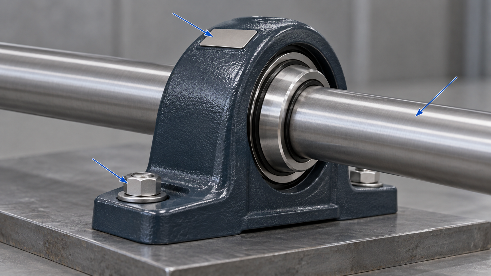
Follow the equipment’s isolation and maintenance procedure before close inspection, measurement or removal. Do not reach into or dismantle a running shaft-support assembly. Start with the available equipment drawing or parts list so that any observations can be compared with the intended configuration.
Record the installed arrangement in enough detail to distinguish the housing from the insert:
- An overall photograph showing the housing form, shaft direction and mounting surface.
- Close photographs of the housing’s markings and any separately visible bearing-insert markings. Record them separately rather than combining both into one assumed part number.
- The shaft diameter and units, plus the existing shaft-locking arrangement identified from its documentation.
- The base or flange dimensions, mounting-hole pattern and shaft-center position relative to the mounting surface, with the measurement points identified.
- The equipment reference, existing part drawings and the reason for the request.
Mark an estimated or inaccessible dimension as such. A photograph taken at an angle cannot reliably establish a hole-center distance. If a marking is hidden, use the documented access procedure or ask the equipment owner for the part record rather than guessing from an exposed prefix.
Determine Which Part You Need to Request
State whether you are asking for a housing, an insert or the assembled unit. This is a supply-scope decision; identifying which damaged parts require replacement remains a maintenance assessment for the equipment.
For a housing-only request, the existing insert reference and the housing’s bearing-seat specification must agree. For an insert-only request, both its housing interface and its shaft interface need confirmation. For a complete unit, the supplier must check the assembly against the mounting geometry and operating conditions, and clarify which accessories are included.
The same shaft diameter does not establish the same housing fit. Similar external shapes or part-number fragments also do not prove cross-manufacturer interchangeability. Use current drawings and the supplier’s identified combination of housing and bearing; keep the measured mounting details alongside those references.
Request a Conveyor Bearing Housing With Clear Scope
Use the conveyor bearing housings range for a housing request. Send the existing housing and mounting details, including photographs, separate component markings, drawings, interface dimensions and quantity.
State explicitly whether the insert will be retained or whether you need the supplier to confirm what components can be supplied. If your request is for a complete unit, clarify that scope before treating a housing listing as an assembly with the bearing included.