
What Does a Conveyor Guide Rail Need to Control?
Choose the rail surface and its contact position first, then match the hardware that holds it there. A rail that touches the wrong part of a container can snag a shoulder or push against a flexible wall. A suitable rail profile still needs a bracket, rod and clamp arrangement that reaches the required position and fits the conveyor frame.
A product side guide rail limits sideways movement as a belt or chain carries the product forward. Its position defines the available product path. This is different from a V-guide on the underside of a conveyor belt, which engages a corresponding groove to help guide the belt itself. Identifying which object needs guidance prevents ordering a belt-guiding part for a product-guiding task.
For replacement work, separate three decisions: where the product should meet the rail, which rail profile provides that contact, and how the rail attaches to the existing supports. Changing one may change the others.
Choose the Rail Profile and Contact Position
Product Clearance and Contact Surface
A straight-sided carton and a bottle with a narrow neck do not present the same guiding surface. Consider the product’s actual side profile at the proposed rail height, including seams, handles, caps, labels and any flexible areas. Contact at a broad, supported sidewall differs from contact at a protruding edge.
Rail height also changes where the lateral force acts. For the same sideways force, contact farther above the base creates a larger overturning moment about a base edge. The supported footprint and weight distribution resist that rotation. A narrow-based container can therefore lean or tip under a contact that a broad carton tolerates; the rail height must be considered with the product, not selected by height alone.
Measure the channel between the two product-facing rail surfaces at the selected contact height. Also measure the product width at that height, including a label seam or shoulder. A bottle’s base width may fit even while its wider shoulder touches both rails.
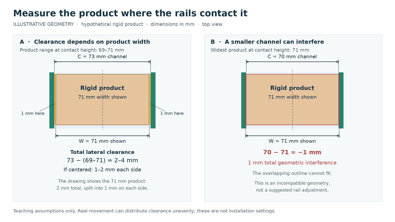
For an illustrative rigid product, suppose the width at that height varies from 69 to 71 mm and the internal rail channel is 73 mm. Total lateral clearance is channel width minus product width: 2 to 4 mm. Only if the product is centered does that become 1 to 2 mm on each side. When it moves to one rail, most of the free space is on the opposite side. These assumed dimensions explain the geometry; they are not recommended settings.
Now put the 71 mm product in a 70 mm channel. The result is 1 mm of geometric interference, rather than a small positive clearance. A rigid product cannot occupy that space without displacement of the rails or product; a flexible package may deform and develop greater contact pressure. Sliding friction at the crowded faces can oppose forward movement. This gives a useful first distinction: rubbing caused by an undersized channel requires a different correction from a protruding joint catching a leading edge.
Check the entrance and exit of the guided section as well. An abrupt rail end or a joint projecting into the path can contact a leading edge even when the straight section has enough room. At a bend or transfer, the product’s swept path may occupy more space than its static width suggests. These are local contact checks, not a reason to redesign an entire conveyor around one replacement part.
Profile, Backing and Adjustment Space
The sliding face and the backing perform different jobs. The face contacts the product; the backing supports the profile and provides an attachment interface. A similar-looking contact face can sit on a different backing, so face width or color is insufficient to identify a replacement. CSTRANS’s documented profile-and-cover examples distinguish a 19 or 23 mm assembled height from a 15 or 19 mm backing-profile height. Measuring only the backing omits the cover’s contribution to the final section. Preserve the dimension points and orientation of the complete section when checking where the replacement contact face will sit.
Record the profile’s cross-section, the face width and the way the backing is retained. A shaped channel, a rod-mounted profile and a profile held in a dedicated holder need different mating hardware. Confirm the stated material from part documentation. Color does not identify the polymer or its suitability for a cleaning chemical.
An adjustable installation needs room for movement as well as a final position. A rod may reach the required rail location but leave too little engagement in its clamp. A handle may strike the frame or adjacent equipment before the full adjustment range is reached. Check both the narrow and wide product settings, including access to the fastening points under the site’s maintenance procedure.
Match Rails, Brackets, Rods and Clamps
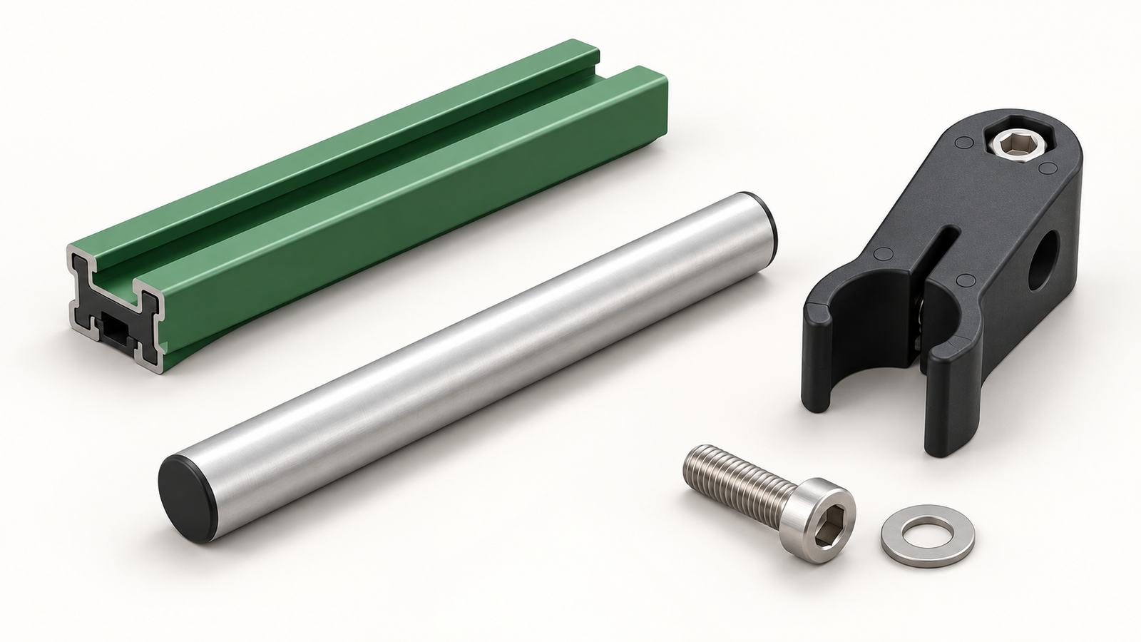
Follow the connection from the contact face back to the frame. The rail attaches to a holder or backing connection; that connection attaches to a support; the support attaches to the conveyor. In a rod-and-clamp arrangement, the rod sets the reach or height and the clamp holds its position. Other arrangements use fixed brackets or slots. The WDS guide rail and bracket catalog illustrates this variety of mounting parts; its interfaces should not be assumed to match another supplier’s parts.
| Connection | What to identify | Why it changes the choice |
|---|---|---|
| Rail to holder or backing | Cross-section, channel or attachment feature, orientation and retention method | A holder must retain the actual profile; matching the visible face alone does not establish fit. |
| Holder to rod or bracket | Connection shape, hole or slot arrangement, fastener and available adjustment | The connection determines how the contact face can be positioned. |
| Rod to clamp | Rod cross-section and dimensions, clamp opening, usable engagement and orientation | A clamp designed for one rod geometry may not grip a different one correctly. |
| Bracket to frame | Mounting pattern, frame interface, fastener specification and access | The rail assembly must attach to the existing structure without treating an unrelated hole pattern as compatible. |
The CSTRANS guide rail bracket range gives concrete interfaces to distinguish: stainless bracket heads are listed in 47 mm short and 75 mm long versions, and the specified round support rod is 12 mm. The head length changes the available assembly envelope; it is not the product-contact height. The rod dimension belongs at the clamp interface, not at the rail face. Round- and square-rod clamps also need to be identified separately.
Support spacing and unsupported reach affect the channel under load. A rail segment can bend between supports, and an extended rod or bracket can deflect as the product presses sideways. A channel measured with no product force is therefore not necessarily the channel maintained during conveying. Outward deflection can let a container lean farther; a shifted or rotated contact face can create a local rub or catch. Moving the face farther from its restraint increases leverage, while stiffness depends on the actual section, material, support and fastening arrangement. A longer head does not by itself establish acceptable overhang or load capacity.
If rubbing is limited to the widest product, compare the measured channel with that product’s contact-height width first. If different products catch at the same point, inspect that local joint, rail end or displaced support. If a product leans when it contacts the rail, consider the force height and support footprint as well as the clearance. These observations narrow the problem before a replacement is chosen; they do not justify changing a setting without the equipment’s assessment procedure.
For a like-for-like replacement, identify the failed or missing part separately from the complete assembly. A worn contact strip may not require a new bracket, while a cracked holder cannot be addressed by changing only the rail face. Confirm which components and fasteners are included in the proposed supply.
Check the Existing Installation Before Ordering
Use the site’s isolation and maintenance procedure before taking close measurements, removing parts or working within the conveyor. A photograph from outside the guarded area can record the general arrangement, but it cannot show a hidden interface reliably.
Create a short record of the installed parts:
- An overall view showing the rail’s position relative to the product and conveyor surface.
- Close views of the rail end profile, backing connection, rod/clamp junction and frame mounting.
- The contact height, product-facing clearance, profile dimensions, rod dimensions and mounting pattern, with measurement points identified.
- Existing part numbers or drawings, conveyor identification, product size range and the reason for replacement.
Distinguish measured dimensions from estimates in the record. If a setting has changed or a part is bent, note that condition so the current position is not mistaken for the intended one. Any change to the guiding arrangement should be assessed by the personnel responsible for the equipment before operation.
Send a Rail-and-Bracket Parts Request
Use the conveyor side guide rail range for the rail profile and the guide rail bracket range for its mounting hardware. For a component request, send the existing part identification, interface measurements, product contact requirements and quantity. State whether you need a contact strip, an individual mounting part or an assembled rail-and-support set so that fit and supply scope can be checked together.