
Conveyor Profile
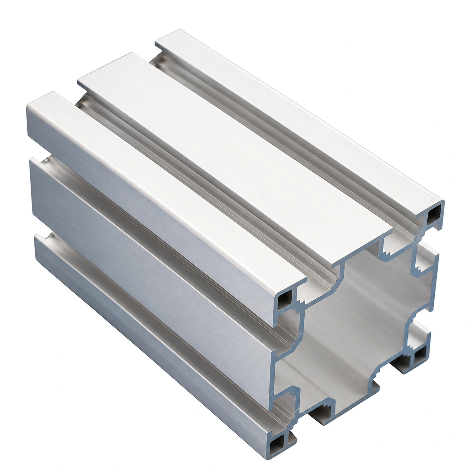
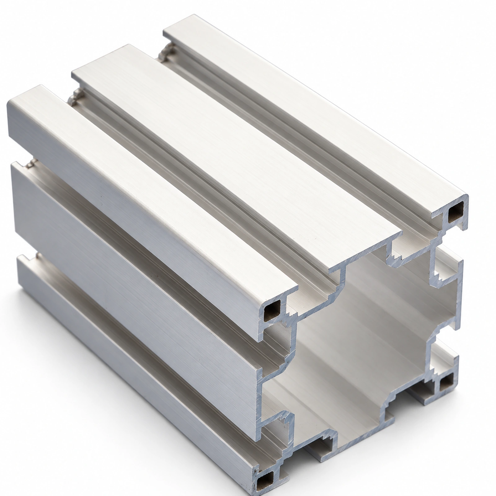
CSTRANS supplies conveyor profile sections for flexible-chain frames: 64×64 and 80×80 uprights with matching foot plates, plus a 40×80 crossbeam profile. These structural sections establish the support geometry beneath the conveying beam. That geometry matters when a straight run, bend or drive end must meet the next section at the intended height and position.
Upright support
Establish the upright support
The 64×64 and 80×80 sections give CSTRANS two upright profile sizes for the frame. Each is paired with a foot-plate arrangement at the floor side. The upright is the vertical reference for the beam above it: its position and installed height affect where the chain carries product relative to adjacent equipment. These section choices let the frame geometry fit the space beneath the conveying route.
Frame width
Set the frame width with a crossbeam
CSTRANS uses its 40×80 profile as a crossbeam. In a support frame, a crossbeam links the upright positions across the conveyor and establishes transverse geometry beneath the conveying route. This matters on a wider or multi-support section: if the support positions drift, the chain-carrying beam and side guides become harder to keep on the intended line. The chain runs on a separate conveyor beam and wear strip above the structural crossbeam.
Route alignment
Keep the support frame aligned with the route
Profile sections serve the fixed frame, while the conveyor beam, wear strip, guides and end units define the chain's running path. CSTRANS can supply these adjacent flexible-chain component families. Coordinating their positions lets the frame support a straight beam, a bend connection or a drive-end interface as one connected route. The profiles provide the reference from which the running components are installed.
Application / Line Context
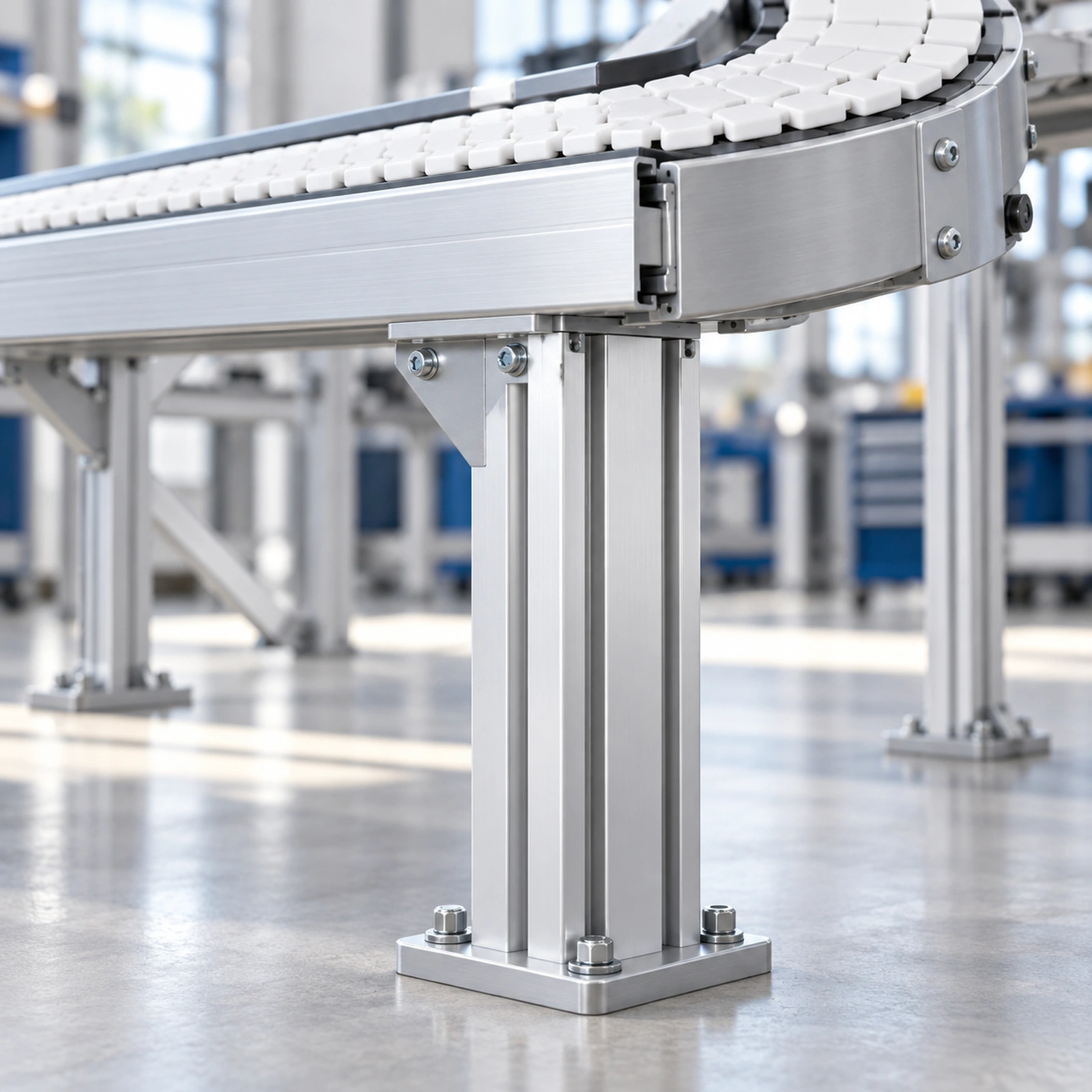
Consider a flexible-chain route that turns before discharging into another machine. Uprights and foot plates place the structural frame on the floor; crossbeams hold the transverse support layout. Above them, the conveyor beam and wear strip carry the chain into the bend, while guides control the product's lateral position. If the frame is set at the wrong height, the discharge can meet the receiving section with an unwanted step even when the chain and sprocket are correctly matched. If support positions change across the bend, the joined beam sections need particular attention so the carrying path remains continuous. At the drive end, frame position also governs where the end unit sits relative to the next conveyor.